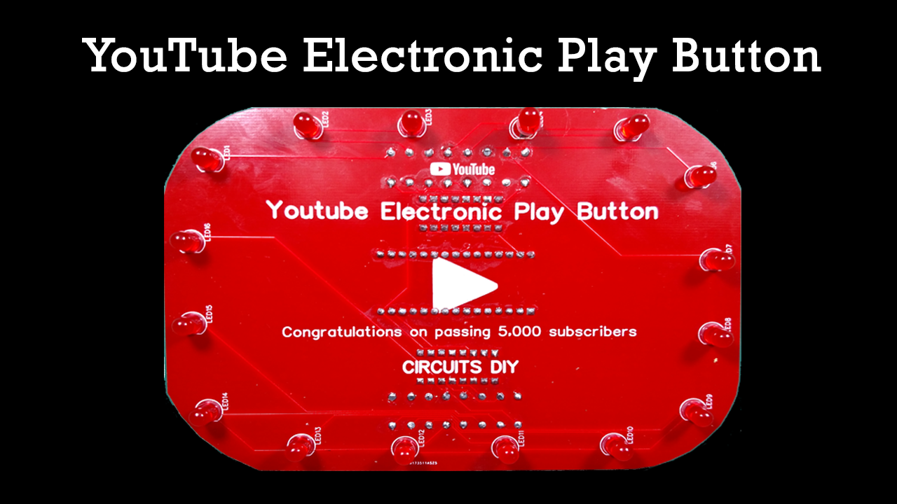
In this tutorial, We will show you how to make an LED controller circuit for the Youtube Play button by using Arduino Nano and two 74HC595 shift register IC. We have made this project using 16 LEDs but we can add as many LEDs as we want (multiple of 8) and add +1 shift register for every extra 8 LEDs we add.
If your project needs to control 16 individual LEDs, that would normally require 16 pins of an Arduino. If you don’t have 16 I/O pins available, this is where the shift register comes in handy. With two shift registers connected in series, we can accomplish the task of controlling the 16 LEDs using only 3 I/O pins.

JLCPCB is the foremost PCB prototype & manufacturing company in china, providing us with the best service we have ever experienced regarding (Quality, Price Service & Time).
Hardware Components
| S. No | Component | Value | Qty |
|---|---|---|---|
| 1. | Arduino with a Cable | Nano | 1 |
| 2. | Soldering Iron | – | 1 |
| 3. | 8 bit Shift Register | 74HC595 | 2 |
| 4. | 8 PIN IC Base | – | 2 |
| 5. | Resistors | 220 ohm | 16 |
| 6. | LED | 5mm | 16 |
| 7. | Header Male/Female | – | 1 |

Working Explanation
In this project, the 16 LEDs are driven with just only 3 Arduino pins. The key element is the shift register. Each 74HC595 shift register can drive up to 8 LEDs and by daisy-chaining registers, it is possible to extend Arduino 3 pins to an infinite number.
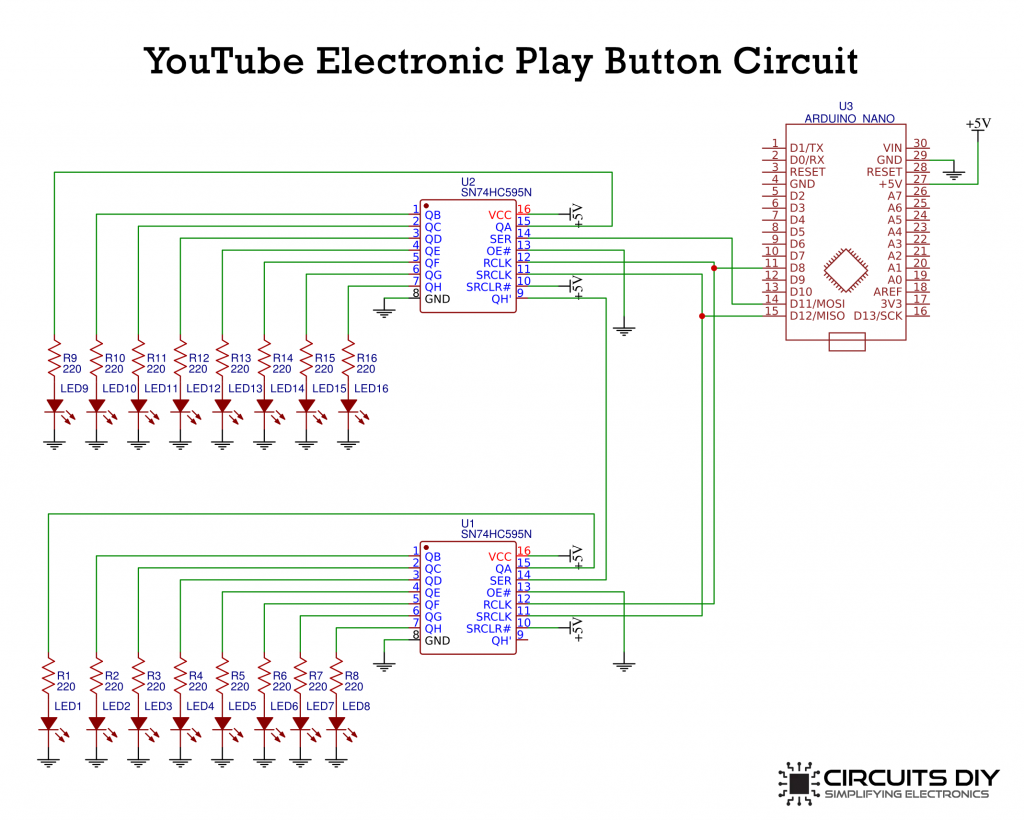
To start with, connect pins 16 (VCC) and 10 (SRCLR) to the 5v pin on the Arduino and connect pins 8 (GND) and 13 (OE) to the GND pin on the Arduino. This will keep the IC in the normal working mode. Now, just connect up all of the output pins to the LEDs, ensuring that a 220Ω resistor is placed before the LEDs to reduce the current and that the cathodes of the LEDs go back to the ground. When placing the LEDs be sure that you connect them in order. So that QA is wired to the first LED, and QH is wired to the last LED, otherwise, our code is not going to light up the LEDs in the correct order.
Circuit Diagram
Arduino Code
int latchPin = 8;
int clockPin = 12;
int dataPin = 11;
int numOfRegisters = 2;
byte* registerState;
long effectId = 0;
long prevEffect = 0;
long effectRepeat = 0;
long effectSpeed = 30;
void setup() {
//Initialize array
registerState = new byte[numOfRegisters];
for (size_t i = 0; i < numOfRegisters; i++) {
registerState[i] = 0;
}
//set pins to output so you can control the shift register
pinMode(latchPin, OUTPUT);
pinMode(clockPin, OUTPUT);
pinMode(dataPin, OUTPUT);
}
void loop() {
do{
effectId = random(6);
} while (effectId == prevEffect);
prevEffect = effectId;
switch (effectId)
{
case 0:
effectRepeat = random(1, 2);
break;
case 1:
effectRepeat = random(1, 2);
break;
case 3:
effectRepeat = random(1, 5);
break;
case 4:
effectRepeat = random(1, 2);
break;
case 5:
effectRepeat = random(1, 2);
break;
}
for (int i = 0; i < effectRepeat; i++) {
effectSpeed = random(10, 90);
switch (effectId)
{
case 0:
effectA(effectSpeed);
break;
case 1:
effectB(effectSpeed);
break;
case 3:
effectC(effectSpeed);
break;
case 4:
effectD(effectSpeed);
break;
case 6:
effectE(effectSpeed);
break;
}
}
}
void effectA(int speed){
for (int i = 0; i < 16; i++){
for (int k = i; k < 16; k++){
regWrite(k, HIGH);
delay(speed);
regWrite(k, LOW);
}
regWrite(i, HIGH);
}
}
void effectB(int speed){
for (int i = 15; i >= 0; i--){
for (int k = 0; k < i; k++){
regWrite(k, HIGH);
delay(speed);
regWrite(k, LOW);
}
regWrite(i, HIGH);
}
}
void effectC(int speed){
int prevI = 0;
for (int i = 0; i < 16; i++){
regWrite(prevI, LOW);
regWrite(i, HIGH);
prevI = i;
delay(speed);
}
for (int i = 15; i >= 0; i--){
regWrite(prevI, LOW);
regWrite(i, HIGH);
prevI = i;
delay(speed);
}
}
void effectD(int speed){
for (int i = 0; i < 8; i++){
for (int k = i; k < 8; k++)
{
regWrite(k, HIGH);
regWrite(15 - k, HIGH);
delay(speed);
regWrite(k, LOW);
regWrite(15 - k, LOW);
}
regWrite(i, HIGH);
regWrite(15 - i, HIGH);
}
}
void effectE(int speed){
for (int i = 7; i >= 0; i--){
for (int k = 0; k <= i; k++)
{
regWrite(k, HIGH);
regWrite(15 - k, HIGH);
delay(speed);
regWrite(k, LOW);
regWrite(15 - k, LOW);
}
regWrite(i, HIGH);
regWrite(15 - i, HIGH);
}
}
void regWrite(int pin, bool state){
//Determines register
int reg = pin / 8;
//Determines pin for actual register
int actualPin = pin - (8 * reg);
//Begin session
digitalWrite(latchPin, LOW);
for (int i = 0; i < numOfRegisters; i++){
//Get actual states for register
byte* states = ®isterState[i];
//Update state
if (i == reg){
bitWrite(*states, actualPin, state);
}
//Write
shiftOut(dataPin, clockPin, MSBFIRST, *states);
}
//End session
digitalWrite(latchPin, HIGH);
}