Introduction
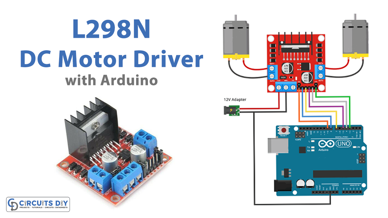
DC motors have wide use in electrical, electronics, and mechanical industries. Shafts, vacuum cleanses, conveyors, washing machines, printing machines, and many other machines used DC motors in them. However, controlling DC motors is need to be understood properly, because every machine has to be derived and controlled differently. Thus, there are different driver ICs available which with the help of microcontrollers like Arduino controlled the DC motors in a better and more precise way. So, in this tutorial, we are going to interface “L298N DC Motor Driver with Arduino UNO”.
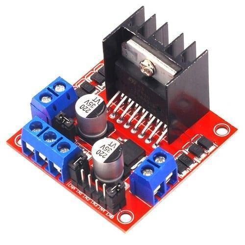
An L298N Motor Driver IC and a 78M05 Voltage Regulator make up the L298N Motor Driver module. Only when the jumper is inserted will the 78M05 Voltage Regulator be activated? The internal circuitry will be powered by the voltage regulator when the power source is less than or equal to 12V, and the 5V pin can be utilized as an output pin to power the microcontroller. When the power supply is greater than 12V, the jumper should be removed and a separate 5V should be provided through the 5V connector to power the internal circuitry.
Hardware Required
| S.no | Component | Value | Qty |
|---|---|---|---|
| 1. | Arduino UNO | – | 1 |
| 2. | USB Cable Type A to B | – | 1 |
| 3 | Jumper Wires | – | – |
| 4. | DC Motor Driver | L298N | 1 |
| 5. | Adopter | 12v | 1 |
Circuit Diagram
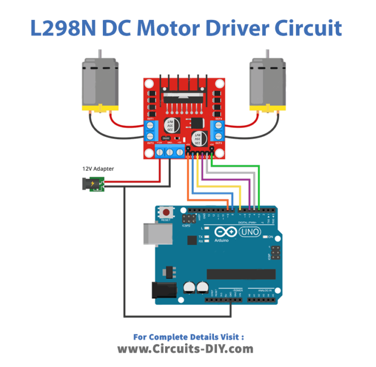
Connection Table
| Arduino | L298N DC Motor Driver |
|---|---|
| VCC | VCC |
| GND | GND |
| D3 | ENB |
| D4 | IN4 |
| D5 | IN3 |
| D7 | IN2 |
| D8 | IN1 |
| D9 | ENA |
Arduino Code
// Motor A connections
int enA = 9;
int in1 = 8;
int in2 = 7;
// Motor B connections
int enB = 3;
int in3 = 5;
int in4 = 4;

void setup() {
	// Set all the motor control pins to outputs
	pinMode(enA, OUTPUT);
	pinMode(enB, OUTPUT);
	pinMode(in1, OUTPUT);
	pinMode(in2, OUTPUT);
	pinMode(in3, OUTPUT);
	pinMode(in4, OUTPUT);

	// Turn off motors - Initial state
	digitalWrite(in1, LOW);
	digitalWrite(in2, LOW);
	digitalWrite(in3, LOW);
	digitalWrite(in4, LOW);
}

void loop() {
	directionControl();
	delay(1000);
	speedControl();
	delay(1000);
}

// This function lets you control spinning direction of motors
void directionControl() {
	// Set motors to maximum speed
	// For PWM maximum possible values are 0 to 255
	analogWrite(enA, 255);
	analogWrite(enB, 255);

	// Turn on motor A & B
	digitalWrite(in1, HIGH);
	digitalWrite(in2, LOW);
	digitalWrite(in3, HIGH);
	digitalWrite(in4, LOW);
	delay(2000);

	// Now change motor directions
	digitalWrite(in1, LOW);
	digitalWrite(in2, HIGH);
	digitalWrite(in3, LOW);
	digitalWrite(in4, HIGH);
	delay(2000);

	// Turn off motors
	digitalWrite(in1, LOW);
	digitalWrite(in2, LOW);
	digitalWrite(in3, LOW);
	digitalWrite(in4, LOW);
}

// This function lets you control speed of the motors
void speedControl() {
	// Turn on motors
	digitalWrite(in1, LOW);
	digitalWrite(in2, HIGH);
	digitalWrite(in3, LOW);
	digitalWrite(in4, HIGH);

	// Accelerate from zero to maximum speed
	for (int i = 0; i < 256; i++) {
		analogWrite(enA, i);
		analogWrite(enB, i);
		delay(20);
	}

	// Decelerate from maximum speed to zero
	for (int i = 255; i >= 0; --i) {
		analogWrite(enA, i);
		analogWrite(enB, i);
		delay(20);
	}

	// Now turn off motors
	digitalWrite(in1, LOW);
	digitalWrite(in2, LOW);
	digitalWrite(in3, LOW);
	digitalWrite(in4, LOW);
}
Working Explanation
To Interface L298N DC Motor Driver Module with Arduino first, make the connections perfectly as described in the table and circuit diagram. Then, after that, write the given code in your Arduino IDE and upload that code to your Arduino. Now, when you give the supply to the circuit, the motor starts to rotate according to the commands provided in the code. For example, those motors start rotating at full speed in one direction, then in the other direction, for two seconds respectively. Then they stop rotating. After that, they accelerate from 0 to maximum speed, then decelerate back to zero. Hence, the motors get controlled according to your code.
Code Explanation
- The Arduino code is quite simple. It does not necessitate the use of any libraries. The code begins by defining the Arduino pins that are attached to the L298N’s control pins.
- In the void setup, we declared the motor pins as the output. Moreover, for their initial state, we turned them off by giving the LOW logic.
- In the void loop, we have called two users to define functions. For example, directionControl() has a function to spin the motors for two seconds at full speed. It then spins the motors in the opposite direction for another two seconds. Finally, the motors are turned off. The function speedControl() accelerates both motors from 0 to maximum speed, then decelerates them back to zero. Finally, the motors are turned off.
Application and Uses
- In robotics for the movement of robots, or robotic cars.
- In the industries for conveyer belts, Printing machines, etc.
- In consumer electronics like vacuum cleaners, etc
Related posts:
 MySQL Database - Arduino Tutorial
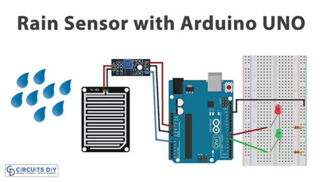 How to Interface Rain Sensor FC-37 or YL-83 with Arduino UNO
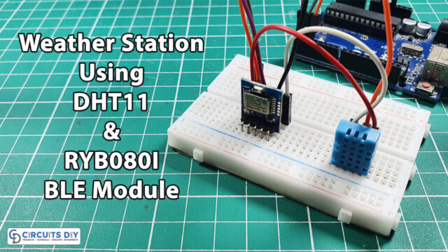 Weather Station using RYB080I Bluetooth Low Energy (BLE) Module with Arduino
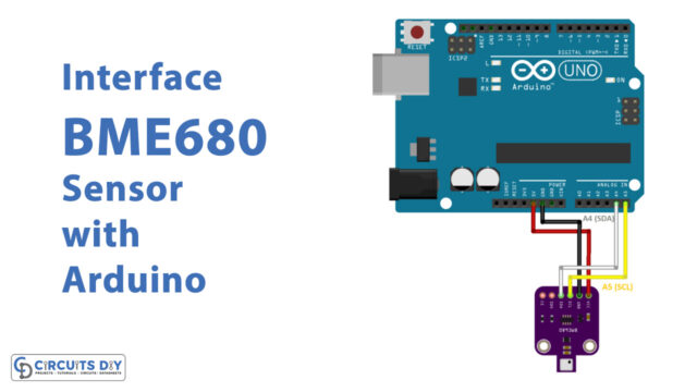 How to Interface BME680 Environmental Sensor with Arduino UNO
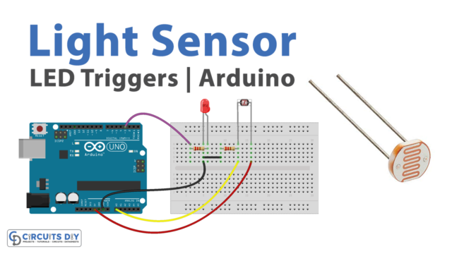 Light Sensor Triggers LED - Arduino Tutorial
 Portable Fine Dust PM10 Analyzer with OLED