Introduction
A Light Dependent Resistor (LDR) controlled LED on an Arduino Uno microcontroller is a circuit that uses an LDR to sense the ambient light level and an LED to indicate the light level. An LDR is a type of resistor whose resistance changes depending on the intensity of the light that it is exposed to.
When the light level is low, the LDR has a high resistance, and when the light level is high, the LDR has a low resistance. The Arduino MCU can use an analog input pin to read the voltage drop across the LDR and convert it to a digital value that represents the resistance. This digital value can then be used to control the state of an LED connected to a digital output pin on the Arduino. When the LDR’s resistance is high (indicating a low light level), the LED can be turned on, and when the LDR’s resistance is low (indicating a high light level), the LED can be turned off.
Hardware Components
You will require the following hardware for Light Sensor Triggers LED with Arduino.
| S.no | Component | Value | Qty |
|---|---|---|---|
| 1. | Arduino UNO | – | 1 |
| 2. | USB Cable Type A to B | – | 1 |
| 3. | Light Sensor | – | 1 |
| 4. | Power Adapter for Arduino | 9V | 1 |
| 5. | LED | – | 1 |
| 6. | Resistor | 220Ω,1kΩ | 1,1 |
| 7. | Breadboard | – | 1 |
| 8. | Jumper Wires | – | 1 |
Light Sensor Triggers LED with Arduino UNO
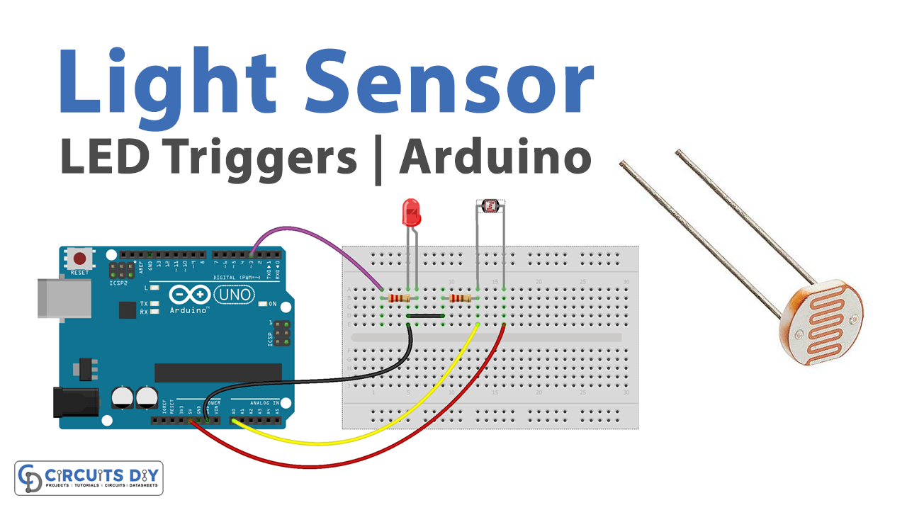
- Connect the LED to the breadboard. Connect the shorter leg of the LED to a row on the breadboard, and the longer leg to a different row. If you are using a 220-ohm resistor, connect it between the LED and the breadboard row as well.
- Connect the LDR to the breadboard. Connect one end of the LDR to a row on the breadboard and the other end to a different row.
- Connect the breadboard to the Arduino. Connect one end of a jumper wire to the row with the shorter leg of the LED and the other end to a digital output pin on the Arduino. Connect another jumper wire from the row with the longer leg of the LED to a ground pin on the Arduino. Connect one end of a jumper wire to one of the rows of the LDR and the other end to an analog input pin on the Arduino. Connect another jumper wire from the other row of the LDR to a power supply pin on the Arduino.
- Open the Arduino software on your computer and create a new sketch by clicking “File” and then “New.”
- In the setup function, set the pin mode for the digital output pin that the LED is connected to by adding the following line of code at the beginning of the sketch:
pinMode(8, OUTPUT);- Replace “8” with the actual pin number of the digital output pin that the LED is connected to.
- In the loop function, read the current value of the LDR using the analogRead function and use it to control the state of the LED. Add the following lines of code to do this:
int ldrValue = analogRead(0);
if (ldrValue < 512) {
  digitalWrite(8, HIGH);
} else {
  digitalWrite(8, LOW);
}
- Replace “0” and “8” with the actual pin numbers of the analog input and digital output pins that the LDR and LED are connected to.
- Upload the sketch to the Arduino and test the LED behavior by changing the light level in the environment.
Note: The threshold value of 512 in the example code is used to divide the range of analog values that the LDR can output (0 to 1023) into two equal parts. The LED will turn on when the LDR value is less than 512, and turn off when the LDR value is greater than or equal to 512. You can adjust this threshold value to change the sensitivity of the circuit.
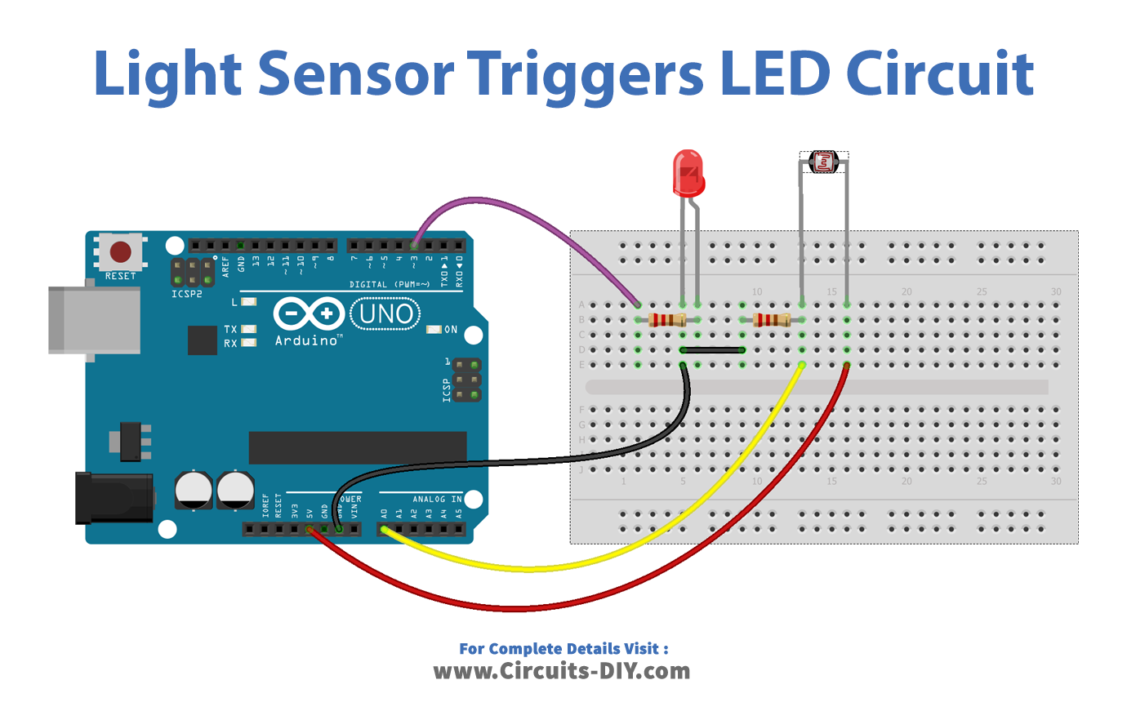
Schematic
Make connections according to the circuit diagram given below.
Installing Arduino IDE
First, you need to install Arduino IDE Software from its official website Arduino. Here is a simple step-by-step guide on “How to install Arduino IDE“.
Code
Now copy the following code and upload it to Arduino IDE Software.
const int LIGHT_SENSOR_PIN = A0; // Arduino pin connected to light sensor's  pin
const int LED_PIN          = 3;  // Arduino pin connected to LED's pin
const int ANALOG_THRESHOLD = 500;

// variables will change:
int analogValue;

void setup() {
  pinMode(LED_PIN, OUTPUT); // set arduino pin to output mode
}

void loop() {
  analogValue = analogRead(LIGHT_SENSOR_PIN); // read the input on analog pin

  if(analogValue < ANALOG_THRESHOLD)
    digitalWrite(LED_PIN, HIGH); // turn on LED
  else
    digitalWrite(LED_PIN, LOW);  // turn off LED
}
Working Explanation
When the Arduino microcontroller is powered on, it runs the code that has been uploaded to it. This code typically includes a setup function that is run once at the beginning and a loop function that is run repeatedly. In the setup function, the pin modes for the input and output pins are set. For the LDR, the pin mode is set to “INPUT” and for the LED, the pin mode is set to “OUTPUT.”
In the loop function, the Arduino reads the current value of the LDR using the analogRead function. This function takes the pin number of the analog input pin as an argument and returns a value between 0 and 1023, with 0 corresponding to 0V and 1023 corresponding to 5V. The returned value is proportional to the voltage drop across the LDR, which is in turn proportional to the LDR’s resistance.
The Arduino then compares the LDR value to a predetermined threshold value. If the LDR value is less than the threshold value, the LED is turned on using the digitalWrite function. If the LDR value is greater than or equal to the threshold value, the LED is turned off. This process is repeated continuously, so the LED’s state is updated in real time as the ambient light level changes.
Applications
- Automatic light switch
- Daylight sensor
- Plant watering system
- Security alarm
- Object tracking
- Robotics
- Educational projects
Conclusion.
We hope you have found this Light Sensor Triggers LED Circuit very useful. If you feel any difficulty in making it feel free to ask anything in the comment section.