Introduction
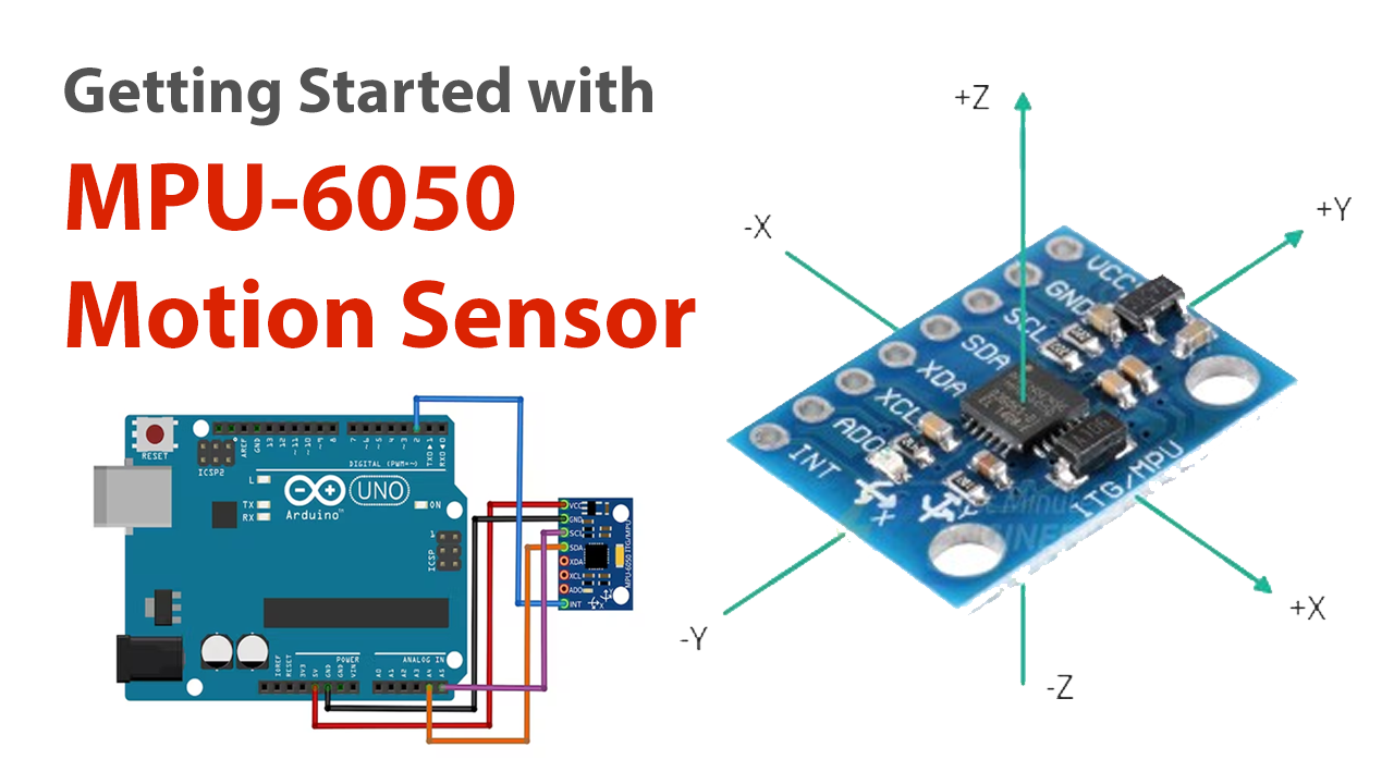
We’ve covered motion sensors and associated circuits for security in a number of our articles. However, motion sensors do a variety of other tasks as well. Since there are several types of motion sensors. The functioning concept of some motion sensors, therefore, extends beyond that of security reasons. Your phone’s motion sensor, for instance, keeps track of movements like tilt, vibration, rotation, and swing. One of the sensors is the MPU-6050 IMU Motion Sensor. And in this post, we’ll discuss how it interfaces with Arduino.
When you turn your phone while watching the video, the phone automatically switches from portrait to landscape mode. Your phone’s accelerometer is responsible for this. Similar to this, several mobile phone games that you play allow you to navigate by using GPS. Because of the gyroscope included in cellphones, this is possible. In essence, accelerometers and gyroscopes are both useful for measuring the acceleration of a moving body or the angular velocity of any object. However, these accelerometers and gyroscopes are integrated into a single sensor. so, let’s discuss this sensor more.
What is IMU (6 DOF) Motion Sensor?
An inertial measurement unit is referred to as an IMU. The combination of an accelerometer and a gyroscope sensor is known as an IMU sensor. It detects and measures movement intensity in terms of acceleration and rotational speeds.

Hardware Components
You will require the following hardware to Interface the MPU-6050 Motion sensor with Arduino.
| S.no | Component | Value | Qty |
|---|---|---|---|
| 1. | Arduino | UNO | 1 |
| 2. | Sensor | MPU-6050 | 1 |
| 3. | Breadboard | – | 1 |
| 4. | Jumper Wires | – | 1 |
Steps Interfacing MPU6050 Motion Sensor with Arduino
In the making of this circuit, you only need Arduino, MPU-6050 IMU Motion Sensor, and some jumper wires. Once you have them all, follow the following steps:
Schematic
Make connections according to the circuit diagram given below.
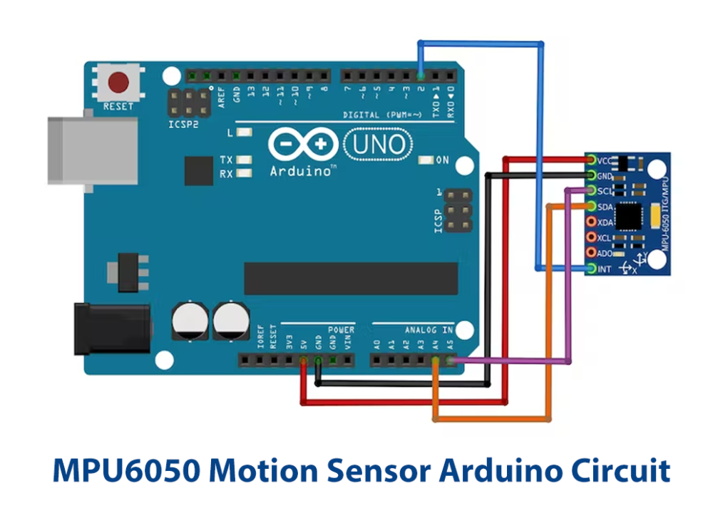
Wiring / Connections
| Arduino UNO | MPU-6050 Sensor |
|---|---|
| 5V | VCC |
| GND | GND |
| A5 | SCL |
| A4 | SDA |
| D2 | INT |
Installing Arduino IDE
First, you need to install Arduino IDE Software from its official website Arduino. Here is a simple step-by-step guide on “How to install Arduino IDE“.
Installing Libraries
Before you start uploading a code, download and unzip the following libraries at /Progam Files(x86)/Arduino/Libraries (default), in order to use the sensor with the Arduino board. Here is a simple step-by-step guide on “How to Add Libraries in Arduino IDE“.
Code
Now copy the following code and upload it to Arduino IDE Software.
*/

// I2Cdev and MPU6050 must be installed as libraries, or else the .cpp/.h files
// for both classes must be in the include path of your project
#include "I2Cdev.h"

#include "MPU6050_6Axis_MotionApps20.h"
//#include "MPU6050.h" // not necessary if using MotionApps include file

// Arduino Wire library is required if I2Cdev I2CDEV_ARDUINO_WIRE implementation
// is used in I2Cdev.h
#if I2CDEV_IMPLEMENTATION == I2CDEV_ARDUINO_WIRE
    #include "Wire.h"
#endif

// class default I2C address is 0x68
// specific I2C addresses may be passed as a parameter here
// AD0 low = 0x68 (default for SparkFun breakout and InvenSense evaluation board)
// AD0 high = 0x69
MPU6050 mpu;
//MPU6050 mpu(0x69); // <-- use for AD0 high

/* =========================================================================
   NOTE: In addition to connection 3.3v, GND, SDA, and SCL, this sketch
   depends on the MPU-6050's INT pin being connected to the Arduino's
   external interrupt #0 pin. On the Arduino Uno and Mega 2560, this is
   digital I/O pin 2.
 * ========================================================================= */

/* =========================================================================
   NOTE: Arduino v1.0.1 with the Leonardo board generates a compile error
   when using Serial.write(buf, len). The Teapot output uses this method.
   The solution requires a modification to the Arduino USBAPI.h file, which
   is fortunately simple, but annoying. This will be fixed in the next IDE
   release. For more info, see these links:

   http://arduino.cc/forum/index.php/topic,109987.0.html
   http://code.google.com/p/arduino/issues/detail?id=958
 * ========================================================================= */


// uncomment "OUTPUT_READABLE_QUATERNION" if you want to see the actual
// quaternion components in a [w, x, y, z] format (not best for parsing
// on a remote host such as Processing or something though)
//#define OUTPUT_READABLE_QUATERNION

// uncomment "OUTPUT_READABLE_EULER" if you want to see Euler angles
// (in degrees) calculated from the quaternions coming from the FIFO.
// Note that Euler angles suffer from gimbal lock (for more info, see
// http://en.wikipedia.org/wiki/Gimbal_lock)
//#define OUTPUT_READABLE_EULER

// uncomment "OUTPUT_READABLE_YAWPITCHROLL" if you want to see the yaw/
// pitch/roll angles (in degrees) calculated from the quaternions coming
// from the FIFO. Note this also requires gravity vector calculations.
// Also note that yaw/pitch/roll angles suffer from gimbal lock (for
// more info, see: http://en.wikipedia.org/wiki/Gimbal_lock)
#define OUTPUT_READABLE_YAWPITCHROLL

// uncomment "OUTPUT_READABLE_REALACCEL" if you want to see acceleration
// components with gravity removed. This acceleration reference frame is
// not compensated for orientation, so +X is always +X according to the
// sensor, just without the effects of gravity. If you want acceleration
// compensated for orientation, us OUTPUT_READABLE_WORLDACCEL instead.
//#define OUTPUT_READABLE_REALACCEL

// uncomment "OUTPUT_READABLE_WORLDACCEL" if you want to see acceleration
// components with gravity removed and adjusted for the world frame of
// reference (yaw is relative to initial orientation, since no magnetometer
// is present in this case). Could be quite handy in some cases.
//#define OUTPUT_READABLE_WORLDACCEL

// uncomment "OUTPUT_TEAPOT" if you want output that matches the
// format used for the InvenSense teapot demo
//#define OUTPUT_TEAPOT


#define LED_PIN 13 // (Arduino is 13, Teensy is 11, Teensy++ is 6)
bool blinkState = false;

// MPU control/status vars
bool dmpReady = false;  // set true if DMP init was successful
uint8_t mpuIntStatus;   // holds actual interrupt status byte from MPU
uint8_t devStatus;      // return status after each device operation (0 = success, !0 = error)
uint16_t packetSize;    // expected DMP packet size (default is 42 bytes)
uint16_t fifoCount;     // count of all bytes currently in FIFO
uint8_t fifoBuffer[64]; // FIFO storage buffer

// orientation/motion vars
Quaternion q;           // [w, x, y, z]         quaternion container
VectorInt16 aa;         // [x, y, z]            accel sensor measurements
VectorInt16 aaReal;     // [x, y, z]            gravity-free accel sensor measurements
VectorInt16 aaWorld;    // [x, y, z]            world-frame accel sensor measurements
VectorFloat gravity;    // [x, y, z]            gravity vector
float euler[3];         // [psi, theta, phi]    Euler angle container
float ypr[3];           // [yaw, pitch, roll]   yaw/pitch/roll container and gravity vector

// packet structure for InvenSense teapot demo
uint8_t teapotPacket[14] = { '$', 0x02, 0,0, 0,0, 0,0, 0,0, 0x00, 0x00, '\r', '\n' };


// ================================================================
// ===               INTERRUPT DETECTION ROUTINE                ===
// ================================================================

volatile bool mpuInterrupt = false;     // indicates whether MPU interrupt pin has gone high
void dmpDataReady() {
    mpuInterrupt = true;
}


// ================================================================
// ===                      INITIAL SETUP                       ===
// ================================================================

void setup() {
    // join I2C bus (I2Cdev library doesn't do this automatically)
    #if I2CDEV_IMPLEMENTATION == I2CDEV_ARDUINO_WIRE
        Wire.begin();
        TWBR = 24; // 400kHz I2C clock (200kHz if CPU is 8MHz)
    #elif I2CDEV_IMPLEMENTATION == I2CDEV_BUILTIN_FASTWIRE
        Fastwire::setup(400, true);
    #endif

    // initialize serial communication
    // (115200 chosen because it is required for Teapot Demo output, but it's
    // really up to you depending on your project)
    Serial.begin(115200);
    while (!Serial); // wait for Leonardo enumeration, others continue immediately

    // NOTE: 8MHz or slower host processors, like the Teensy @ 3.3v or Ardunio
    // Pro Mini running at 3.3v, cannot handle this baud rate reliably due to
    // the baud timing being too misaligned with processor ticks. You must use
    // 38400 or slower in these cases, or use some kind of external separate
    // crystal solution for the UART timer.

    // initialize device
    Serial.println(F("Initializing I2C devices..."));
    mpu.initialize();

    // verify connection
    Serial.println(F("Testing device connections..."));
    Serial.println(mpu.testConnection() ? F("MPU6050 connection successful") : F("MPU6050 connection failed"));

    // wait for ready
    Serial.println(F("\nSend any character to begin DMP programming and demo: "));
    while (Serial.available() && Serial.read()); // empty buffer
    while (!Serial.available());                 // wait for data
    while (Serial.available() && Serial.read()); // empty buffer again

    // load and configure the DMP
    Serial.println(F("Initializing DMP..."));
    devStatus = mpu.dmpInitialize();

    // supply your own gyro offsets here, scaled for min sensitivity
    mpu.setXGyroOffset(220);
    mpu.setYGyroOffset(76);
    mpu.setZGyroOffset(-85);
    mpu.setZAccelOffset(1788); // 1688 factory default for my test chip

    // make sure it worked (returns 0 if so)
    if (devStatus == 0) {
        // turn on the DMP, now that it's ready
        Serial.println(F("Enabling DMP..."));
        mpu.setDMPEnabled(true);

        // enable Arduino interrupt detection
        Serial.println(F("Enabling interrupt detection (Arduino external interrupt 0)..."));
        attachInterrupt(0, dmpDataReady, RISING);
        mpuIntStatus = mpu.getIntStatus();

        // set our DMP Ready flag so the main loop() function knows it's okay to use it
        Serial.println(F("DMP ready! Waiting for first interrupt..."));
        dmpReady = true;

        // get expected DMP packet size for later comparison
        packetSize = mpu.dmpGetFIFOPacketSize();
    } else {
        // ERROR!
        // 1 = initial memory load failed
        // 2 = DMP configuration updates failed
        // (if it's going to break, usually the code will be 1)
        Serial.print(F("DMP Initialization failed (code "));
        Serial.print(devStatus);
        Serial.println(F(")"));
    }

    // configure LED for output
    pinMode(LED_PIN, OUTPUT);
}


// ================================================================
// ===                    MAIN PROGRAM LOOP                     ===
// ================================================================

void loop() {
    // if programming failed, don't try to do anything
    if (!dmpReady) return;

    // wait for MPU interrupt or extra packet(s) available
    while (!mpuInterrupt && fifoCount < packetSize) {
        // other program behavior stuff here
        // .
        // .
        // .
        // if you are really paranoid you can frequently test in between other
        // stuff to see if mpuInterrupt is true, and if so, "break;" from the
        // while() loop to immediately process the MPU data
        // .
        // .
        // .
    }

    // reset interrupt flag and get INT_STATUS byte
    mpuInterrupt = false;
    mpuIntStatus = mpu.getIntStatus();

    // get current FIFO count
    fifoCount = mpu.getFIFOCount();

    // check for overflow (this should never happen unless our code is too inefficient)
    if ((mpuIntStatus & 0x10) || fifoCount == 1024) {
        // reset so we can continue cleanly
        mpu.resetFIFO();
        Serial.println(F("FIFO overflow!"));

    // otherwise, check for DMP data ready interrupt (this should happen frequently)
    } else if (mpuIntStatus & 0x02) {
        // wait for correct available data length, should be a VERY short wait
        while (fifoCount < packetSize) fifoCount = mpu.getFIFOCount();

        // read a packet from FIFO
        mpu.getFIFOBytes(fifoBuffer, packetSize);

        // track FIFO count here in case there is > 1 packet available
        // (this lets us immediately read more without waiting for an interrupt)
        fifoCount -= packetSize;

        #ifdef OUTPUT_READABLE_QUATERNION
            // display quaternion values in easy matrix form: w x y z
            mpu.dmpGetQuaternion(&q, fifoBuffer);
            Serial.print("quat\t");
            Serial.print(q.w);
            Serial.print("\t");
            Serial.print(q.x);
            Serial.print("\t");
            Serial.print(q.y);
            Serial.print("\t");
            Serial.println(q.z);
        #endif

        #ifdef OUTPUT_READABLE_EULER
            // display Euler angles in degrees
            mpu.dmpGetQuaternion(&q, fifoBuffer);
            mpu.dmpGetEuler(euler, &q);
            Serial.print("euler\t");
            Serial.print(euler[0] * 180/M_PI);
            Serial.print("\t");
            Serial.print(euler[1] * 180/M_PI);
            Serial.print("\t");
            Serial.println(euler[2] * 180/M_PI);
        #endif

        #ifdef OUTPUT_READABLE_YAWPITCHROLL
            // display Euler angles in degrees
            mpu.dmpGetQuaternion(&q, fifoBuffer);
            mpu.dmpGetGravity(&gravity, &q);
            mpu.dmpGetYawPitchRoll(ypr, &q, &gravity);
            Serial.print("ypr\t");
            Serial.print(ypr[0] * 180/M_PI);
            Serial.print("\t");
            Serial.print(ypr[1] * 180/M_PI);
            Serial.print("\t");
            Serial.println(ypr[2] * 180/M_PI);
        #endif

        #ifdef OUTPUT_READABLE_REALACCEL
            // display real acceleration, adjusted to remove gravity
            mpu.dmpGetQuaternion(&q, fifoBuffer);
            mpu.dmpGetAccel(&aa, fifoBuffer);
            mpu.dmpGetGravity(&gravity, &q);
            mpu.dmpGetLinearAccel(&aaReal, &aa, &gravity);
            Serial.print("areal\t");
            Serial.print(aaReal.x);
            Serial.print("\t");
            Serial.print(aaReal.y);
            Serial.print("\t");
            Serial.println(aaReal.z);
        #endif

        #ifdef OUTPUT_READABLE_WORLDACCEL
            // display initial world-frame acceleration, adjusted to remove gravity
            // and rotated based on known orientation from quaternion
            mpu.dmpGetQuaternion(&q, fifoBuffer);
            mpu.dmpGetAccel(&aa, fifoBuffer);
            mpu.dmpGetGravity(&gravity, &q);
            mpu.dmpGetLinearAccel(&aaReal, &aa, &gravity);
            mpu.dmpGetLinearAccelInWorld(&aaWorld, &aaReal, &q);
            Serial.print("aworld\t");
            Serial.print(aaWorld.x);
            Serial.print("\t");
            Serial.print(aaWorld.y);
            Serial.print("\t");
            Serial.println(aaWorld.z);
        #endif

        #ifdef OUTPUT_TEAPOT
            // display quaternion values in InvenSense Teapot demo format:
            teapotPacket[2] = fifoBuffer[0];
            teapotPacket[3] = fifoBuffer[1];
            teapotPacket[4] = fifoBuffer[4];
            teapotPacket[5] = fifoBuffer[5];
            teapotPacket[6] = fifoBuffer[8];
            teapotPacket[7] = fifoBuffer[9];
            teapotPacket[8] = fifoBuffer[12];
            teapotPacket[9] = fifoBuffer[13];
            Serial.write(teapotPacket, 14);
            teapotPacket[11]++; // packetCount, loops at 0xFF on purpose
        #endif

        // blink LED to indicate activity
        blinkState = !blinkState;
        digitalWrite(LED_PIN, blinkState);
    }
}
Let’s Test It
After that, you may run the code by immediately uploading it to an Arduino board and turning it on. Open the serial monitor. Press the RESET button if you don’t see the message “Initializing I2C devices…” on your screen. Now it should function.
You may view values using the serial monitor. To see various readings, tilt the sensor or adjust its orientation.
Working Explanation
An internal motion processor is included in the I MPU 6050. It analyses the accelerometer and gyroscope data to provide us with precise 3D values.
The accelerometer calculates acceleration or the rate at which an object’s motion changes. It detects both static forces, such as gravity, and dynamic forces, such as vibrations or movement. The X, Y, and Z axes of acceleration are measured by the MPU-6050 in this circuit. Rotational velocity is measured by the gyroscope This is the change in angular position along the X, Y, and Z axes over time. This enables us to determine an object’s orientation.
Applications
- Gaming devices
- Fitness devices
- Robotics; etc
Conclusion.
We hope you have found this Circuit very useful. If you feel any difficulty in making it feel free to ask anything in the comment section.