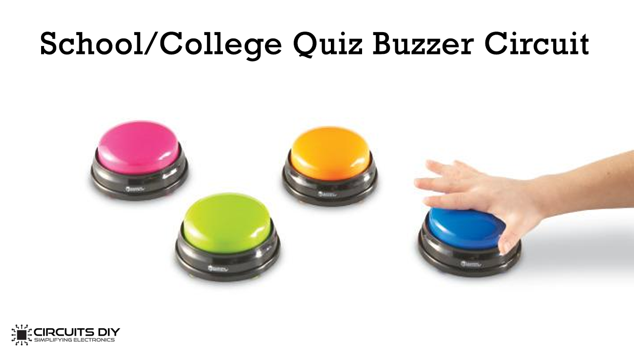
In this electronic project, we are going to make a “School/College Quiz Buzzer Circuit” using 555 Timer IC. A quiz is an essential event in any institution to test the participants’ knowledge. To increase the difficulty, it also examines the participant’s spontaneity in which the reaction time of the participants is also necessary. So showing the person who is ready to answer the question first has to push the buzzer.
It is also difficult for a judge or organizer to identify the first person who pushed the buzzer ON, of the participant’s race to answer the question. So here we have added a feature in which if someone presses the buzzer first then the entire remaining participants, “buzzer gets disabled and the buzzer will not sound again until it presses the reset button.

Hardware Components
The following components are required to make Quiz Buzzer Circuit
| S.No | Component | Value | Qty |
|---|---|---|---|
| 1. | Breadboard | – | 1 |
| 2. | Battery | 9v | 1 |
| 3. | Connecting Wires | – | 1 |
| 4. | IC | NE555 Timer | 3 |
| 5. | NPN Transistor | BC547 | 1 |
| 6. | Diode | 1N4007 | 3 |
| 7. | Resistors | 10k,1k, 500 ohms | 4,1,3 |
| 8. | Tactile Switch | – | 5 |
| 9. | Buzzer | – | 1 |
| 10. | LED | 5mm | 6 |
555 IC Pinout

For a detailed description of pinout, dimension features, and specifications download the datasheet of 555 Timer
Quiz Buzzer Circuit
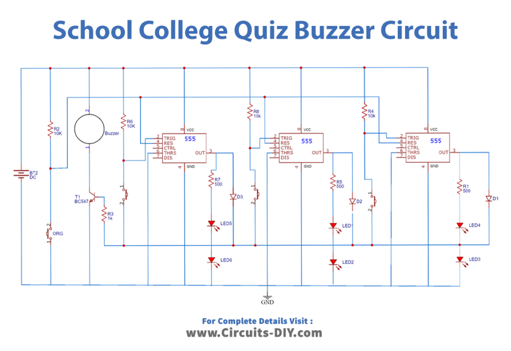
Operation
Here in this circuit diagram, we have used three 555 timer IC in a bistable configuration. The important part is that each 555 IC will have its stable state controlled by separate buttons, which the participants will access. Another single button controls the other steady-state of the entire timer ICs in stock, which an organizer can access to reset the whole circuit. When you press any of the buttons P1, P2, or P3, the corresponding TRIGGER pin gets low, the timer shifts its stable state, and the output pin of the similar timer goes high. And the Green LED of the corresponding participant turns on and the buzzer beeps.
The operation is that when you activate the first stable state of any one-timer, it disables the remaining counters. The biased diode connected to the output pin of the set timers gets forward biased, making the remaining button terminals go high. Therefore, even if you press other buttons after that, the corresponding timer’s pin sees only a high signal. Thus, the buttons work only after resetting the circuit. You can control the buzzer using the NPN BC547 transistor, whose control signal is the common trigger to which you connect the buttons. Also, you ground the buttons through the internal diode of the transistor.
Working Explanation
The 5V or 9V battery powers the entire circuit. Initially, the circuit is in a RESET state and waiting for the trigger signal. Thus, when the participant presses the button, the corresponding timer changes its condition and output go high, and the buzzer sounds to show the button press. The image shows that after pressing the S1 button, it disables the remaining buttons. Now, when we press the RESET button ORG, the circuit goes to the initial state and again waits for the next TRIGGER. The red LED shows the organizer of the first person to press the button. This process can continue several times. If the buzzer is unnecessary, it can remove BC547 and the buzzer from the circuit. To add more participants in the circuit cascade more 555 timer ICs, diodes, and LEDs.