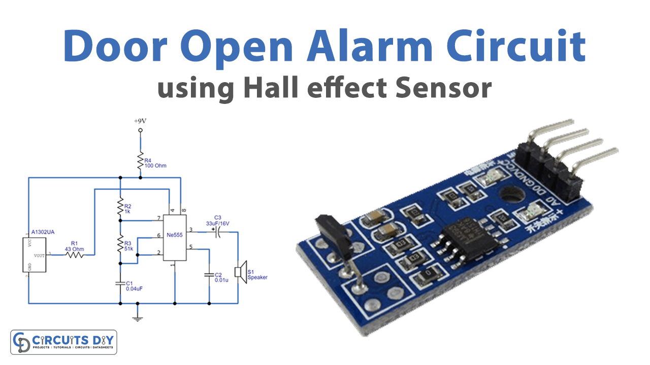
In this tutorial, we are going to make a “Door Open Alarm Circuit using Hall effect Sensor”.
A door alarm is a very common and useful device for security purposes. They are used to detect whether the door is open or closed. Often, we have seen some door alarms in the refrigerator that produced a different sound when they activate. Here we design a simple door open alarm circuit using a hall-effect sensor with timer IC 555. This circuit utilizes an A1302 hall-effect sensor IC and it is optimized to accurately provide a voltage output that is proportional to an applied magnetic field. Here timer IC 555 is configured as an astable multivibrator and the Reset pin is connected to the output pin of Hall effect sensor A1302, whenever the magnetic field is removed from this sensor then near Vcc voltage appears on the output pin. It can detect open doors and produce a loud alert sound through a 0.5 watts loudspeaker.
Hardware Required
| S.no | Component | Value | Qty |
|---|---|---|---|
| 1. | Hall Effect Sensor IC | 1302UA | 1 |
| 2. | Timer IC | LM555 | 1 |
| 3. | Loud Speaker | 8Ω/0.5W | 1 |
| 4. | Resistor | 100Ω, 1KΩ, 51KΩ, 43Ω | 1, 1, 1, 1 |
| 5. | Capacitor | 0.01uF, 0.04uF | 1, 1 |
| 6. | Electrolytic Capacitor | 33uF/16V | 1 |
| 7. | Small Magnet | – | 1 |
| 8. | Connecting Wires | – | – |
| 9. | Battery | 9V | 1 |
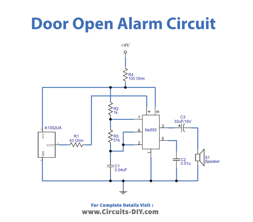
Circuit Diagram
Working Explanation
As shown in the circuit, timer IC 555 works as a pulse oscillator, and the hall-effect sensor is placed to work as a switch. When we put the magnate near the hall Sensor the hall sensor senses the magnetic field and generates a Low signal as an output. Here when the door is closed (During a near magnet situation) hall effect sensor acts as an open switch and there is no voltage at Reset pin 4 of timer IC 555. Now when we take the magnate far from the hall sensor then the hall sensor generates a High signal as an output, here when the door is open (During a far-from-magnet situation) hall-effect sensor acts as a closed switch and gives output voltage near Vcc and hence the Reset pin 4 gets bias. Timer IC 555 is employed as an astable multivibrator and output is connected with an 8Ω / 0.5 watts loudspeaker; it starts to oscillate pulse signal because Reset pin 4 of IC 555 is an active low pin. Now there are two timing resistors R2, R3, and one timing capacitor C1 to generate desired output pulse duration. We can get different alert sound tones from loudspeakers by changing the values of resistors and capacitors.
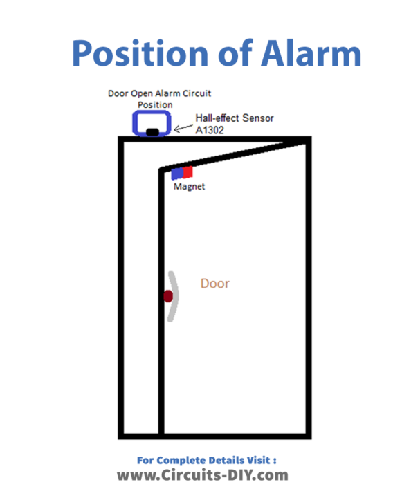
Position of Alarm
Applications
The circuit can be installed in a workshop, office, or home for security purposes.