In this tutorial, we are going to make a wireless power transfer project. As the name suggests wireless power transfer is a process in which electrical energy is transferred from one system to another without using wires or any other physical contact but through electromagnetic waves. It can light up a 3V bulb wirelessly, you can also use an array of LEDs. This project is divided into two parts, transmitter, and receiver. You can also use this project as a wireless charger for several devices by doing some changes to this circuit.
The phenomena of wireless power transmission include the inductive energy that transmits from a transmitter coil to a receiver coil through an oscillating magnetic field. The current supplied by a DC power source is transformed into a high-frequency AC current, this process is done in the transmitter part of this circuit.

Hardware Components
The following components are required to make Wireless Power Transfer Circuit
| S.no | Component | Value | Qty |
|---|---|---|---|
| 1. | Battery | 3V | |
| 2. | Resistors | 1.2K, 10K, 47Ω | 1,1 |
| 3. | Ceramic Capacitors | 3300pF, 10nF, 100nF | 1,1,1 |
| 4. | IC | NE555 timer | 1 |
| 5. | Transistor | BD139 | 1 |
| 6. | Inductor | – | 2 |
| 7. | Lamp/Bulb | 3V | 1 |
NE555 IC Pinout

For a detailed description of pinout, dimension features, and specifications download the datasheet of 555 Timer
BD139 Pinout
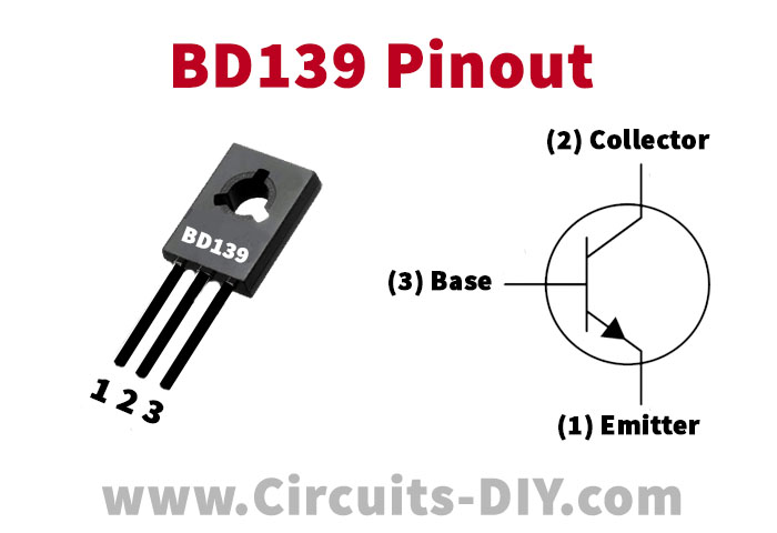
For a detailed description of pinout, dimension features, and specifications download the datasheet of BD139
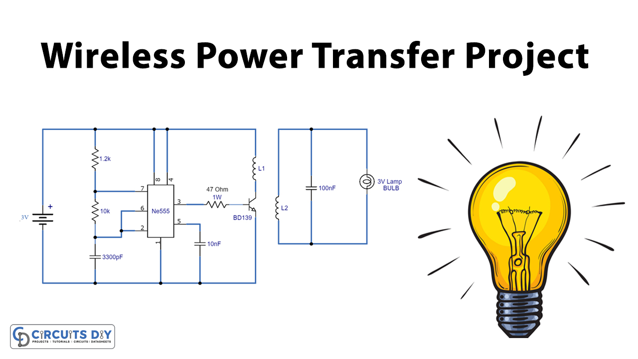
Wireless Power Transfer Circuit
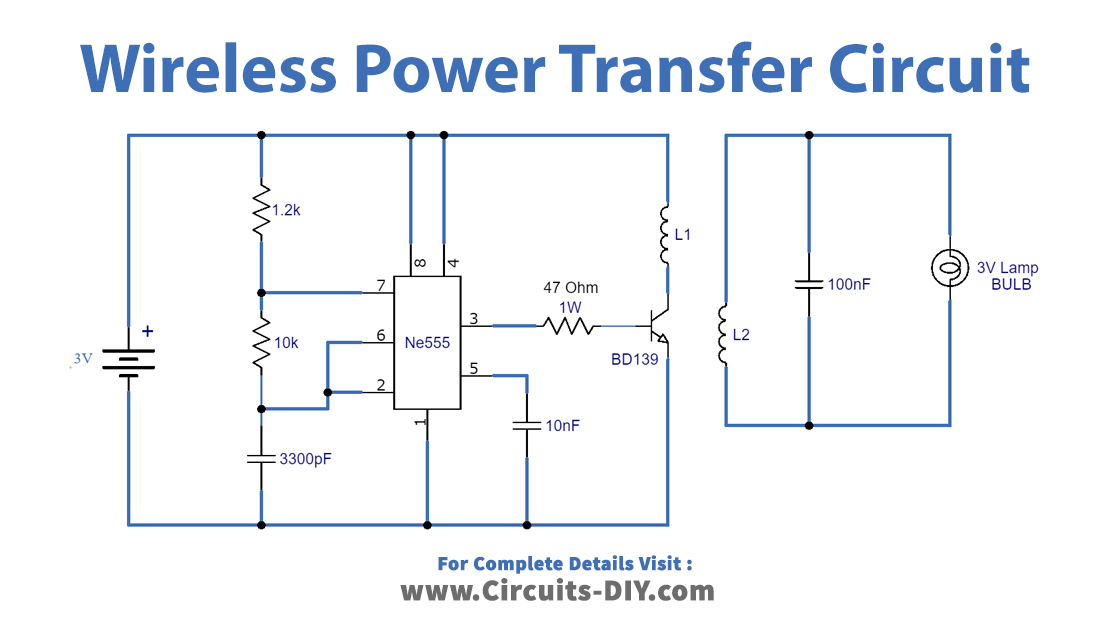
Working Explanation
This circuit has two parts, the transmitter circuit has a 555 timer IC along with a few components. This part is producing a pulse through timing components such as resistors and capacitors. The pulse is generated from IC which is fed into the transistor through a 47Ω/1watt resistor. The collector terminal of this transistor is connected with a coil which turns the DC bias magnetic flux with the help of the transistor.
The receiver part also has a coil that turns magnetic flux into alternate power. This part contains a 100nF capacitor and a 3V bulb. When the receiver circuit’s coil is located near the magnetic field generated from the transmitter circuit, the magnetic field can induce an AC current in the receiving coil. The electrons in this part convert the AC current back to DC current which provides the desired power and turns the Bulb/Lamp ON.
Both coils are built by winding 30 turns of SWG enameled copper wire with a 5cm diameter. This circuit works on a few centimeters but the range can be increased by making changes in the coil. You can also increase the input voltage at the transmitter side if more voltage is required at the receiver circuit
Applications and Uses
- Charging devices wirelessly
- Helps in making Waterproof products
- DC Fans
- Wireless Lamp