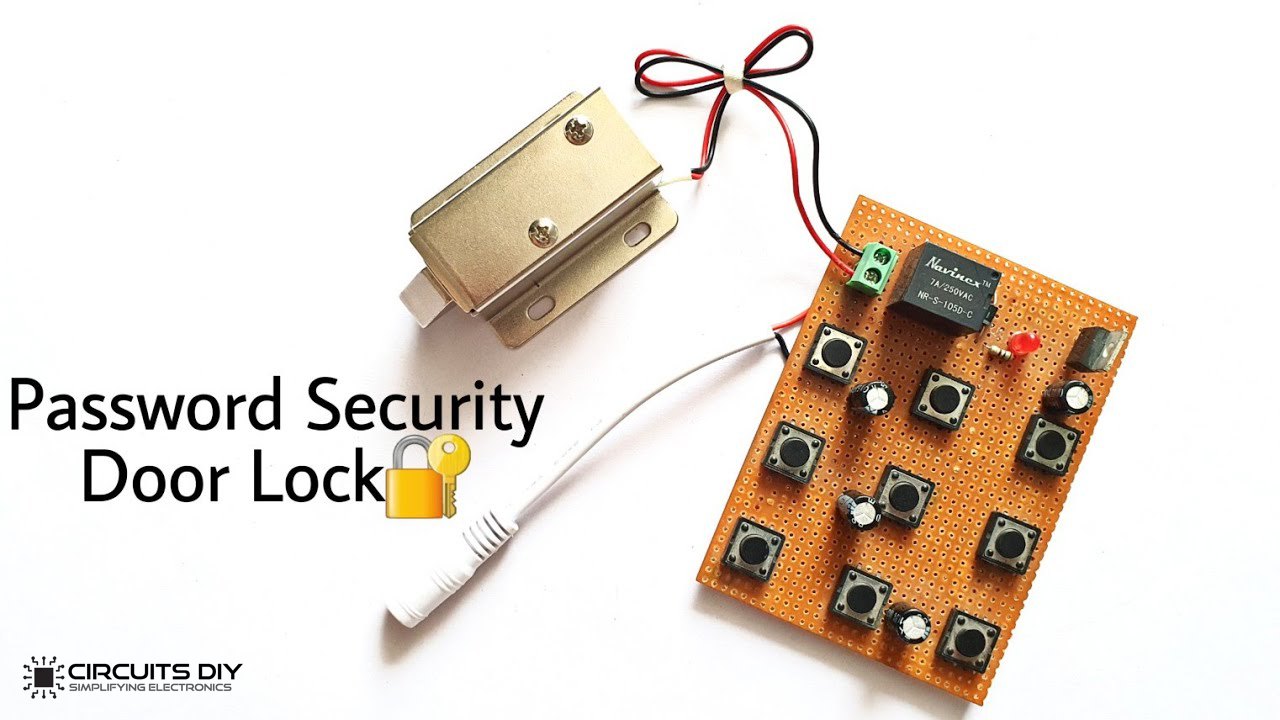
This is an intriguing DIY detailed instruction tutorial on “Electronic Door Lock Password Security Circuit” using IRF540 MOSFET. It can use as a security check system to constrain access to only certain people with security codes.
The fundamental standard of this circuit is that the door lock only opens when the switches in series are squeezed at a time. However, if any switch other than the password key switches is pressed, the circuit reset itself. Meanwhile, if the switches in series are pressed in order, the capacitor turned on the relay which consequently opens the electronic lock.
Hardware Components
The following components are required to make a Door Lock Circuit
| S.no | Components | Value | Qty |
|---|---|---|---|
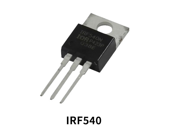
| 1 | MOSFET | IRF540 | 1 |
| 2 | Diode | 1N4007 | 1 |
| 3 | Electrolytic Capacitor | 470µF | 4 |
| 4 | Relay | 5V | 1 |
| 5 | PCB | – | 1 |
| 6 | LED | – | 1 |
| 7 | Resistor | 470Ω | 1 |
| 8 | Switch | – | 9 |
| 9 | Battery | 9V – 12V | 1 |
IRF540 Pinout
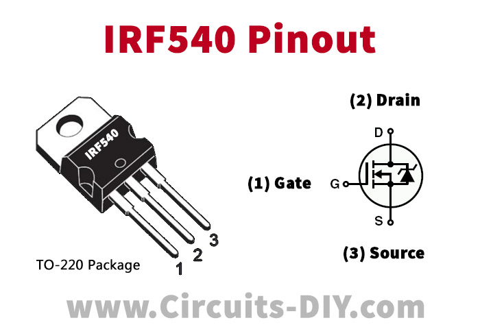
For a detailed description of pinout, dimension features, and specifications download the datasheet of IRF540
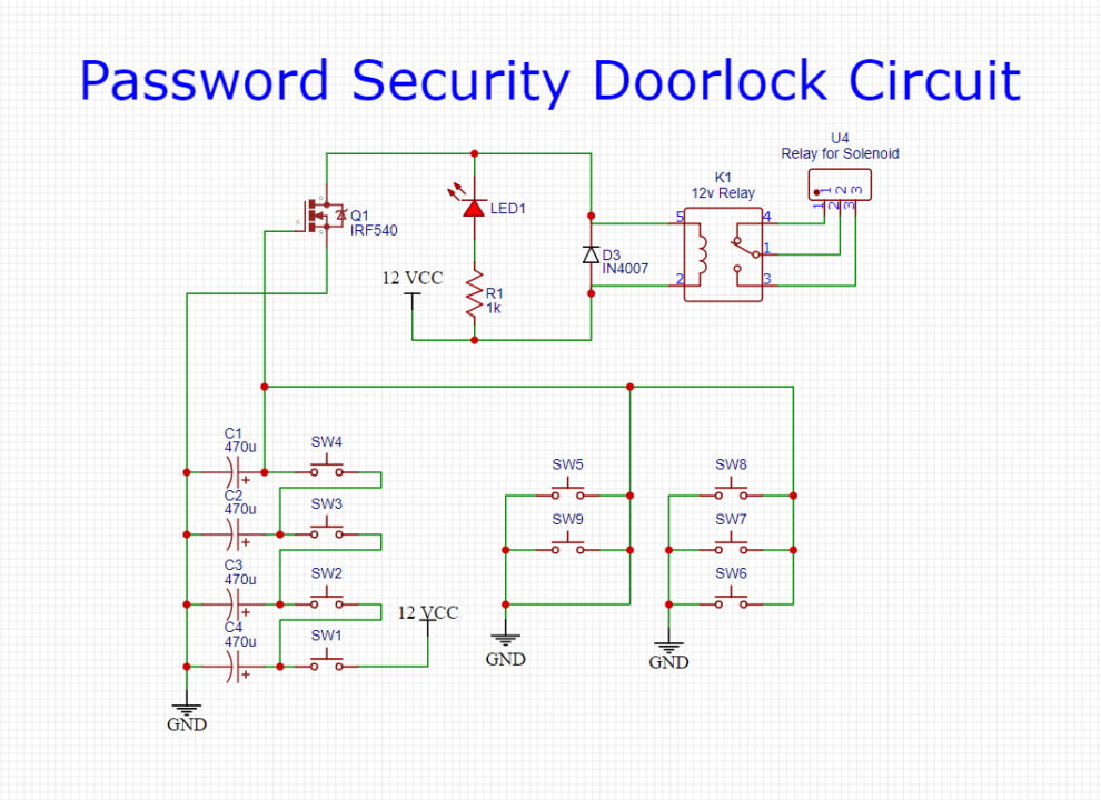
Door Lock Circuit
Useful Steps
Step# 01
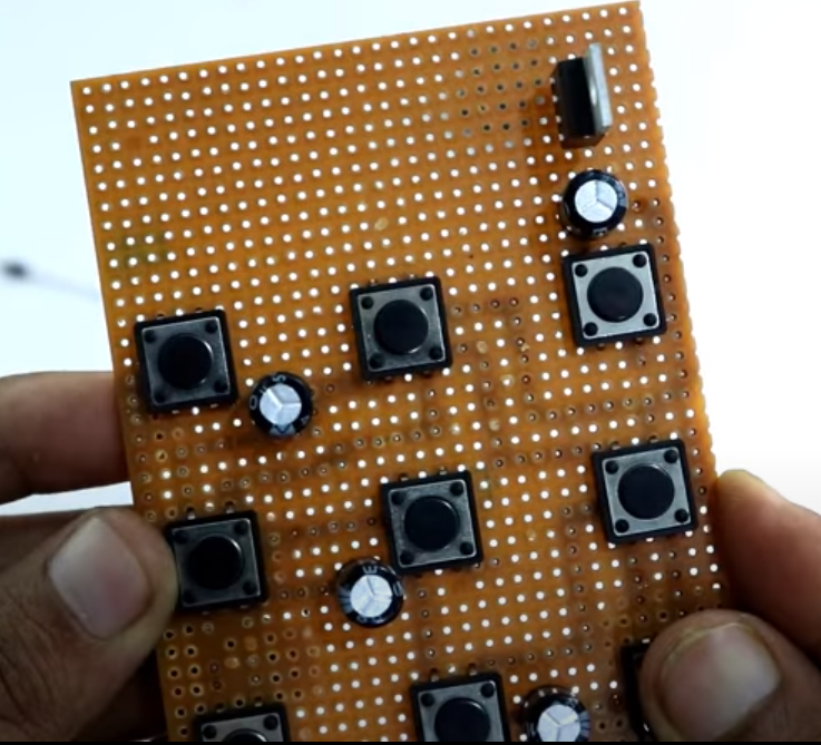
First, take zero PCB and install all the nine switches on the PCB board. After Installing all nine switches, solder all the pins.
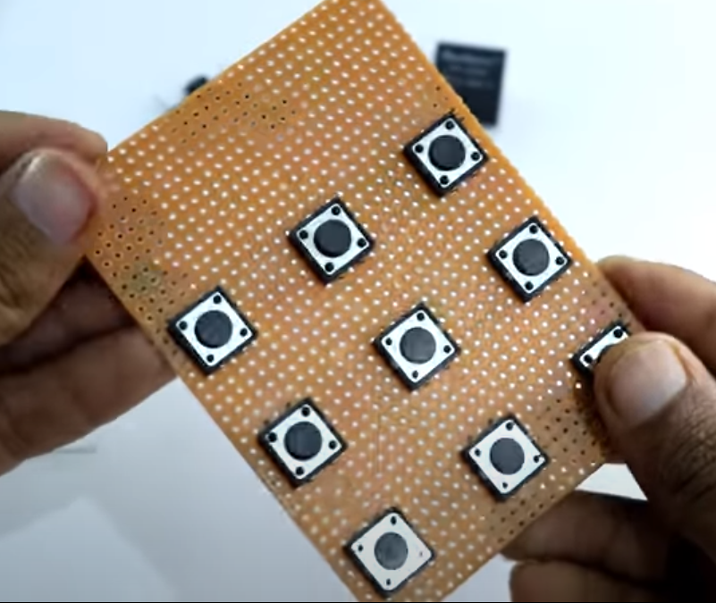
Step# 02
After soldering all, select any 4 four pins to make a password key. And left all the other 5 switches for reset and connect all these reset pins in parallel.
Step# 03
Now connect capacitors between the series of password key switches.
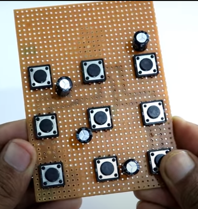
Step# 04
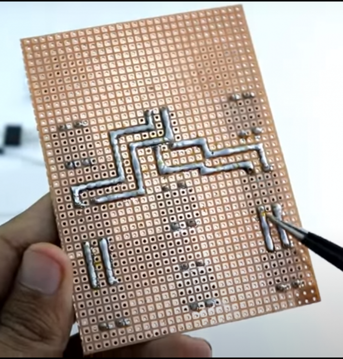
Now install MOSFET on the PCB Board. Connect the source pin of MOSFET on the capacitor’s negative terminal while the gate pin on the positive terminal of the 4th capacitor.
Step# 05
Install 5V relay in the PCB Board.
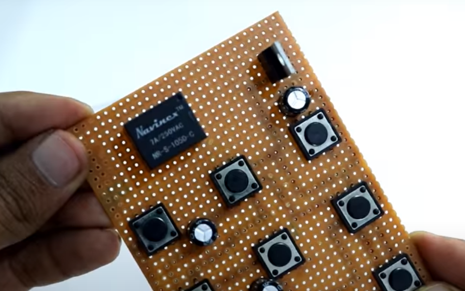
Step# 06
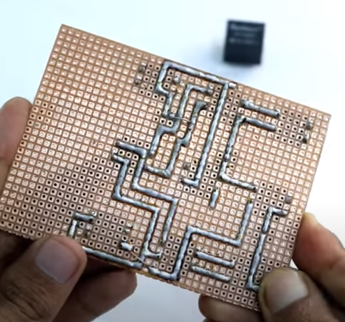
Connect the 1N4007 diode on the relay coil pin to avoid reverse current flow in the circuit. Now connect 470Ω resistor in between the Vcc and LED positive. Connect LED positive on the resistor and negative on the MOSFET drain pin.
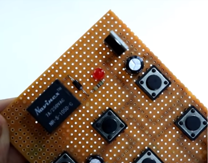
Step# 07
In the last step, connect the circuit with a battery or any other 9V – 12V power source. Connect the negative terminal on the ground of the circuit and the positive on the diode cathode. Connect an electronic lock to the relay with the help of a terminal block.
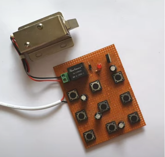
Circuit Operation
The password security door lock circuit operates in a manner that, when I press the first switch, the first capacitor will take charge from the power source or battery. And when I press the second switch, the half charge of the first capacitor will transfer to the second capacitor. This cycle will run up to the last capacitor of the circuits. Hence, the fourth capacitor activates the 5V relay which consequently unlocks the electronic lock.
Applications and Uses
- It utilizes in security checking system
- Door locking