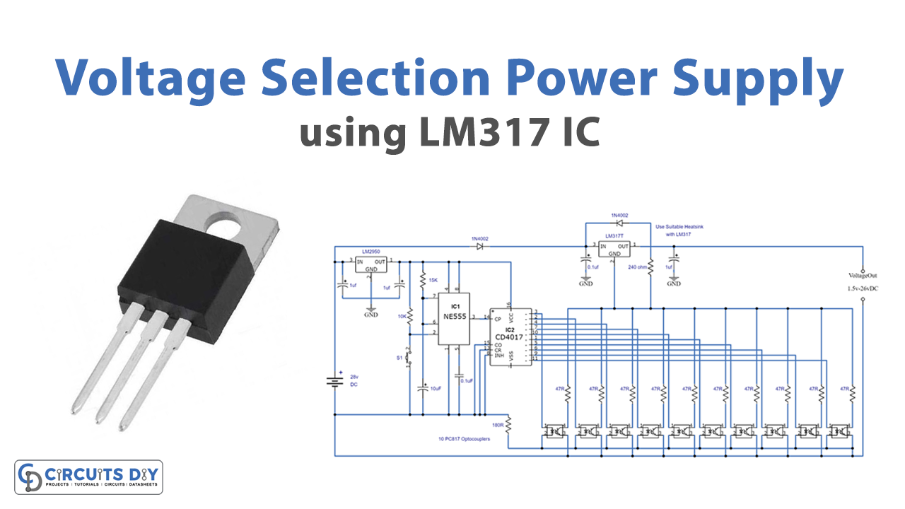
This is a circuit of LM317 Single Push Voltage Selection Power Supply. There are lots of other options available for an adjustable power supply but sometimes it takes time to adjust the variable resistor again and again if we are working on multiple circuits. But with the help of this circuit, this problem can be solved. To change the desired voltage, you just have to touch a Push switch S1 and the voltage will be changed.
There are 10 options of different voltages available to choose from. This circuit can provide output voltages ranging from 1.5V to 26V DC with a max current of 1.5A. Because of the variety of output voltages and a convenient way of changing them, this circuit is perfect for labs and other purposes.
Hardware Components
The following components are required to make LM317 Power Supply Circuit
| S.no | Components | Value | Qty |
|---|---|---|---|
| 1. | DC voltage | 28V | 1 |
| 2. | IC | LM2950-5.0 | 1 |
| 3. | IC | NE555 Timer | 1 |
| 4. | Decade Counter IC | CD4017 | 1 |
| 5. | Voltage Regulator IC | LM317T | 1 |
| 6. | Resistor | 10K, 4.7K, 4.3K, 3.3K, 2.7K, 2.2K, 1.5K, 910R, 750R, 180R, 360R, 47R, 240Ω, 15K | 1, 1, 1, 1, 1, 1, 1, 1, 1, 1, 1, 1, 1, 1 |
| 7. | Electrolytic Capacitor | 1µF, 10µF | 3, 1 |
| 8. | Ceramic Capacitor | 0.1µF | 2 |
| 9. | Optocouplers | PC817 | 10 |
| 10. | Diodes | 1N4002 | 2 |
| 11. | Battery | 24V | 1 |
| 12. | Connecting Wires | – | 1 |
| 13. | Breadboard | – | 1 |
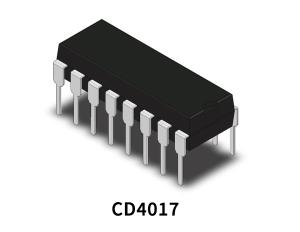
CD4017 Pinout
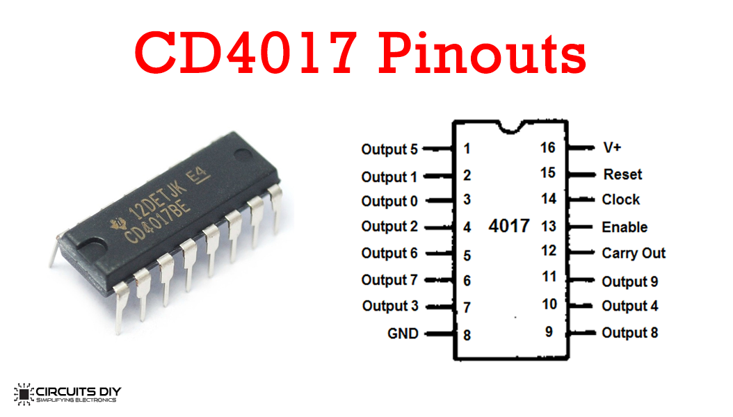
For a detailed description of pinout, dimension features, and specifications download the datasheet of CD4017
555 IC Pinout

For a detailed description of pinout, dimension features, and specifications download the datasheet of 555 Timer
LM317T Pinout
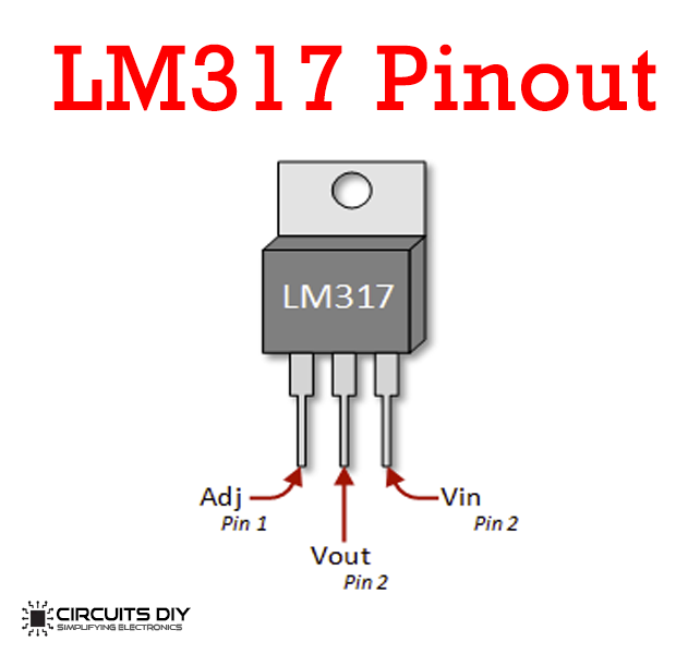
For a detailed description of pinout, dimension features, and specifications download the datasheet of LM317T
LM317 Power Supply Circuit
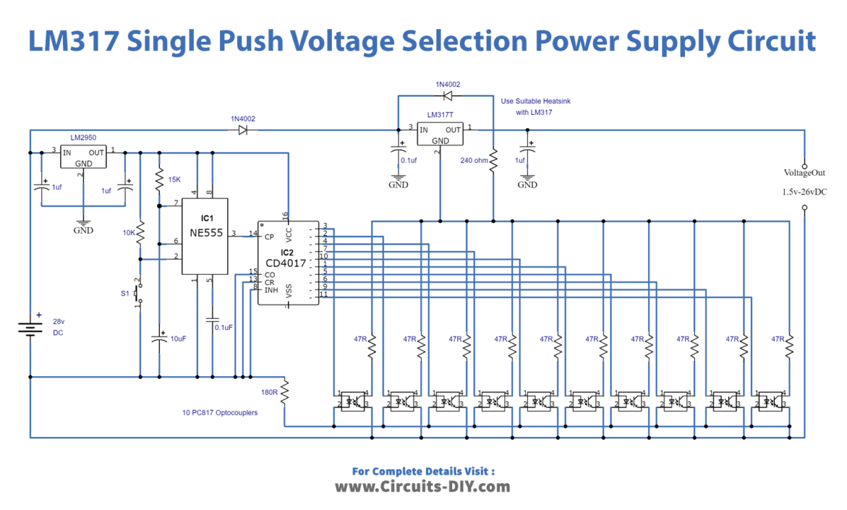
Working Explanation
The operating voltage of this circuit is 28V DC with 2 Amperes of input current. This input signal is going into a low-power voltage regulator IC LM2950-5.0. You can not use more than 28V for this circuit because this IC’s maximum voltage is 29V.
IC1 is a 555 timer IC that is generating clock pulses on the input of the decade counter IC CD 4017. The frequency of these pulses depends on the resistor and the capacitor. In this circuit, we have used a 10K resistor and 10uF capacitor. CD4017 IC is generating 10 outputs, each of these outputs is sent into a current limiting resistor and a PC817 optocoupler. The purpose of LM317T is to provide a regulated output voltage that can be selected by pushing the switch S1. Those 10 output voltages are 1.5V, 3V, 5V, 6V, 9V, 12V, 15V, 18V, 24V and 26V
Use a suitable heatsink with LM317T IC because it can get warm during the operation.
Applications and Uses
This circuit has a wide range of applications in electronic laboratories, projects, op-amp or oscillator circuits, DC motors, etc.