Introduction
Take control of your health with a Heart Rate Monitor Alarm Circuit! This innovative circuit allows you to track your heart rate in real-time and alerts you if it falls outside of your desired range. Whether you’re a fitness enthusiast, recovering from an injury, or want to stay on top of your health, this circuit is the perfect solution. And the best part? You can build it yourself with just a few basic components. So, let’s get started and give your heart the attention it deserves!
Hardware Required
You will require the following hardware for Building a Heart Rate Monitor, Alarm Circuit.
Figure 1 Circuit Table
| S.no | Components | Value | QTY |
|---|---|---|---|
| 1 | IC 1 | IC a, IC b | 1, 1 |
| 2 | IC 2 | 4060 | 1 |
| 3 | Polar Capacitor | 1uF / 25V | 2 |
| 4 | Non Polar Capacitor | 0.1uF | 2 |
| 5 | Resistor | 1k, 68k, 680k, 6k8, 33k, 150E | 1, 2, 2, 1, 1 |
| 6 | Variable Resistor | 470E Preset | 1 |
| 7 | Zener | 3v | 1 |
| 8 | LED | – | 1 |
| 9 | Diode 1 | IR photo Diode Transmitter | 1 |
| 10 | Diode 2 | IR photo Diode Receiver | 1 |
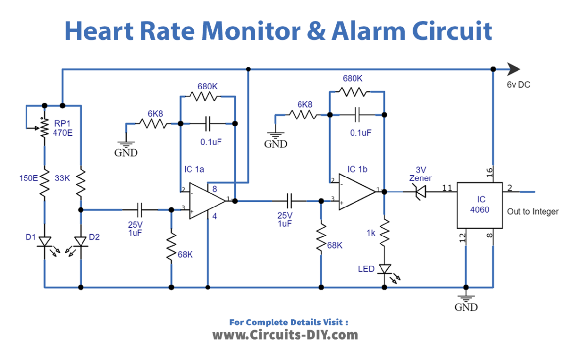
Figure 2 Circuit Table
| S.no | Components | Value | QTY |
|---|---|---|---|
| 1 | IC | 741, 555 Timer | 1 |
| 2 | Polar Capacitor | 2u2, 22u | 1, 1 |
| 3 | Non Polar Capacitor | 68n, 47n, 100n, | 1, 1, 2 |
| 4 | Resistor | 47, 5k7, 3k3, 10k, 1k, | 1, 1, 1, 3, 1 |
| 5 | Variable Resistor | 10k, 100k | 1, 1 |
| 6 | Transistor | BC547 | 1 |
| 7 | Diode | – | 3 |
| 8 | Zener | 3v | 1 |
| 9 | Piezo Buzzer | – | 1 |
Working Explanation
.The circuit consists of two stages:
- A heart rate sensor/processor
- An alarm system
Heart Rate Sensor/Processor
This circuit stage consists of a heart rate sensor with a built-in frequency multiplier and an integrator-comparator. The frequency multiplier, which uses the IC 4060, amplifies the heart rate signal into a high-frequency signal. This high-frequency signal is then fed into an integrator, which converts the digitally varying frequency into a continuously varying exponential analog signal. This analog signal represents the patient’s heart rate and is used in the next stage of the circuit to trigger an alarm if necessary.
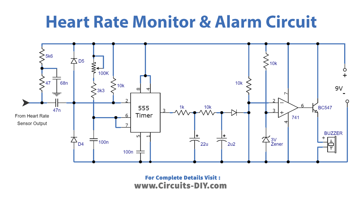
Alarm System
The alarm system uses a comparator, such as the IC 741, to compare the analog heart rate signal to a reference voltage. The comparator is set with a 10k preset so that the voltage at the comparator’s output remains just below the reference voltage when the heart rate is in a safe range. If the heart rate goes outside of this range, the voltage at the comparator’s output exceeds the reference voltage, triggering the output of the comparator to go high and sounding the alarm. By using a different comparator circuit or adjusting the reference voltage, we can set the alarm to sound if the heart rate is too high or too low.
Final Words
Building a heart rate monitor alarm circuit is a great way to keep track of your heart rate during physical activity or medical monitoring. Using a few simple components, you can construct a circuit that will accurately measure your heart rate and sound an alarm if your heart rate exceeds a certain threshold. Whether you’re a fitness enthusiast, a medical professional, or just looking for a fun DIY project, this circuit is a great choice. Happy building, and stay healthy!