Introduction
In this project, we are going to make a fun and amazing circuit that is called the Musical horn circuit. It is the circuit used in vehicles particularly in bicycles for producing an amplified horn or sound for alerting those that come across the path of the bicycle. The horns that came in old bicycles have now been replaced by some modern musical horns. This idea would allow you to replace your bicycle’s old-fashioned horn with the new one
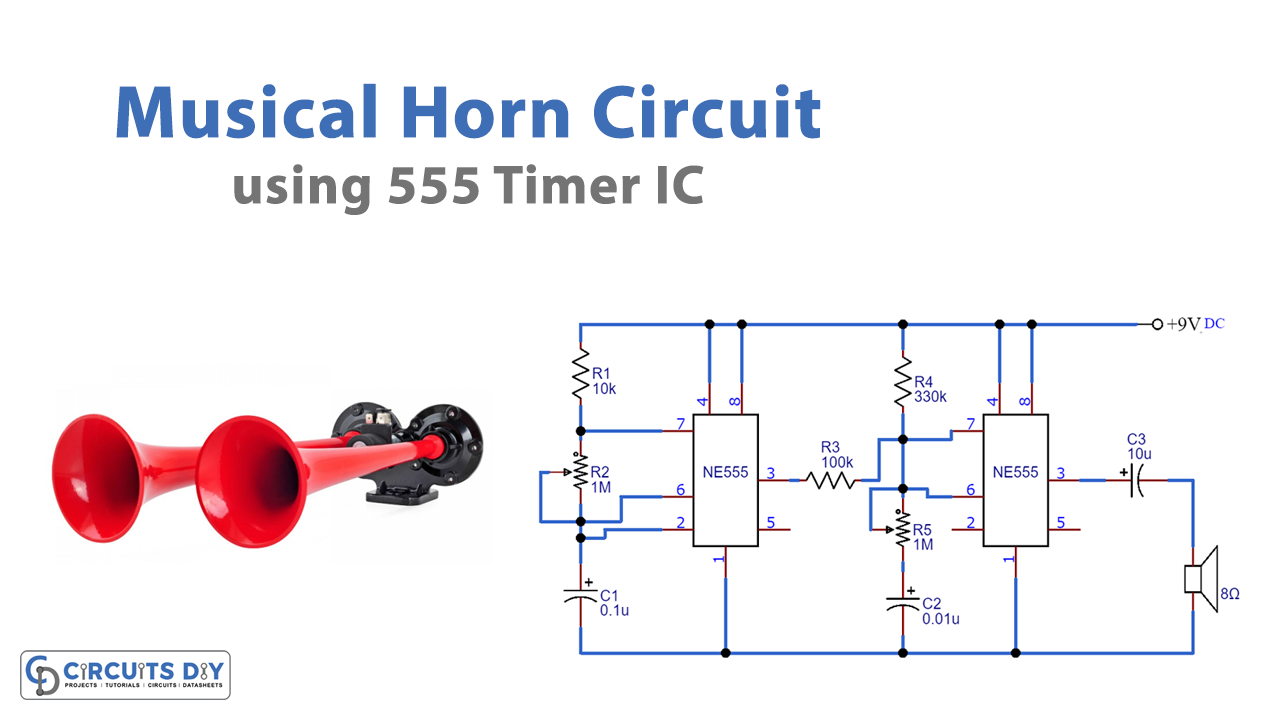
This project is suitable for new electronic students, enthusiasts, and fanciers. The circuit is easy to build. It contains two NE555 timers ICs that work in astable mode. Before turning ON the circuit make sure to mount the IC on its holder and all the capacitors must be rated 15V.
Hardware Required
| S.no | Component | Value | Qty |
|---|---|---|---|
| 1. | Breadboard | – | 1 |
| 2. | IC | NE555 Timer | 2 |
| 3. | Potentiometer | 1M | 2 |
| 4. | Resistor | 10K, 100K, 330K | 1, 1, 1 |
| 5. | Capacitor | 0.1uF, 0.01uF | 1, 1 |
| 6. | Speaker | 8 Ohm | 1 |
| 7. | Battery | 9v | 1 |
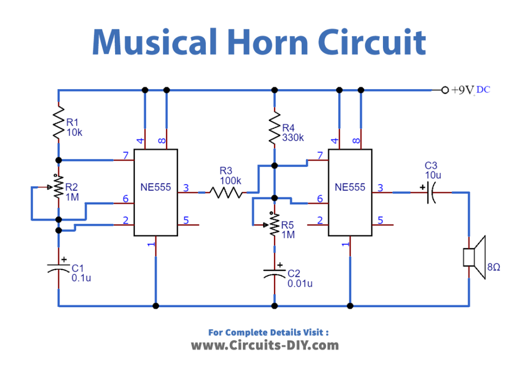
Circuit Diagram
Working Explanation
When the circuit is powered with a 9V PP3 battery, the first multivibrator IC got active and gives its output to the discharge pin which is Pin 7 of the second multivibrator IC. Note that both the ICs are working in a stable multivibrator mode. The collective outcome of both multivibrators generates a musical tone and output. The sound or tone can be regulated by the potentiometers R2 and R5.
Application and Uses
- It is used on bicycles
- It may be used in different vehicles like trucks, etc
- With some modification, it can be used as a doorbell