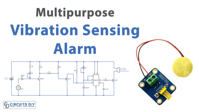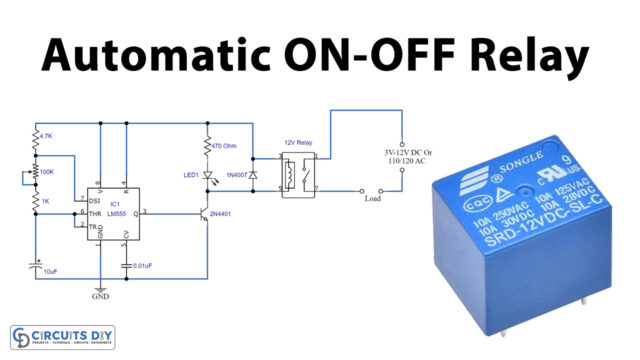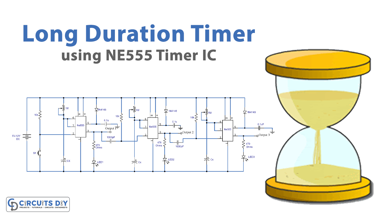
In this tutorial, we are going to make a circuit of Long Duration Timer (Max Two Weeks Duration). This circuit is adjustable and can work for a few minutes or up to two weeks or 14 days. We are using three ICs, one transistor, and a few other external components.
These timer circuits are very useful for electronic projects and other electric appliances and since this circuit can be used for two weeks it has a wide range of applications. It doesn’t cost much and is reliable. There is a relay switch at the output of this circuit which can drive AC/DC loads of your choice.
Hardware Components
The following components are required to make the Duration Timer Circuit
| S.no | Components | Value | Qty |
|---|---|---|---|
| 1. | DC Supply | 5-12V | 1 |
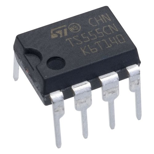
| 2. | IC | NE555 Timer | 1 |
| 3. | Variable Resistor | 1M | 3 |
| 4. | Diodes | 1N4148 | 3 |
| 5. | Switch | – | 1 |
| 6. | LED | – | 3 |
| 7. | Resistor | 10K, 470Ω | 3, 3 |
| 8. | Ceramic Capacitor | 0.1µF, 1000pF | 3, 2 |
| 9. | Electrolytic Capacitor | no value show | 3 |
555 IC Pinout

For a detailed description of pinout, dimension features, and specifications download the datasheet of 555 Timer
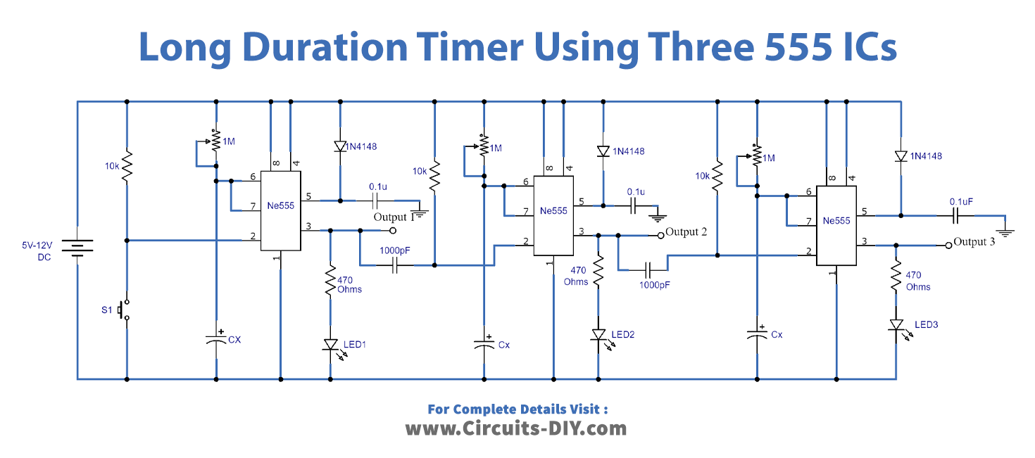
Duration Timer Circuit
Working Explanation
IC1 is a 555 timer that is working here as an oscillator and is providing clock pulses to the input pin of IC2. The carry-out CO pin of IC2 is connected with the clock input of IC3. In this way, these three ICs are working, giving their output to the input of another and the final output is what drives the relay. And the relay in this circuit is used to drive any AC/DC load.
The time duration of this circuit is adjusted through a variable resistor of 5M ohms. We have connected this with a 555 timer IC so that it gives the clock pulses accordingly.
To test the time, we have connected an LED at the output of the IC1 as a visual indicator of its pulses. You can set the desired time duration of this circuit by checking the LED blinking. For example, if you want to adjust the circuit for 1 day, adjust the 5M resistor to generate a pulse after 15 minutes and if you want it for 2 days set the 555 timer IC to provide each pulse after 30 minutes, and so on.
Circuit Testing
After the completion of this circuit, it is essential to perform a simple test to make sure everything is working properly. In order to do that, you have to adjust the variable resistor to its minimum value. The LED will blink faster due to which the output relay will turn on and off fast and you will understand if the circuit is working properly