A remote control circuit allows the operation of devices that are out of convenient reach for direct operation of controls. It is an electronic device used to operate another device from a distance, usually wirelessly. Most remote controls around us, use IR for signal transmission. An IR remote control for home appliances helps you easily connect to your devices and operate them from the comfort of your bed or your chair. They function best only when used from a short distance. Here we design a circuit to control home appliances through IR remote control. You can use any IR remote to control this circuit, by using it we can turn on/off any device.
Hardware Required
| S.No | Components | Value | Qty |
|---|---|---|---|
| 1 | Decade counter IC | CD4027 | 1 |
| 2 | Timer IC | ne555 | 1 |
| 3 | IR Sensor | TSOP1736 | 1 |
| 4 | SPDT Relay | – | 1 |
| 5 | Positive Regulator IC | 7805 | 1 |
| 6 | Diode | 1N4007 | 1 |
| 7 | Transistor | SL-100 | 1 |
| 8 | Resistor | 1KΩ, 470Ω, 100Ω, 100KΩ, 330Ω | 3, 1, 1, 2, 1 |
| 9 | Capacitor | 100uF/16V, 10uF, 0.01uF | 1, 2, 2 |
| 10 | LED | – | 4 |
| 11 | Connecting Wires | – | – |
| 12 | Battery | 9V | 1 |
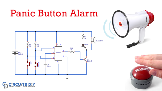
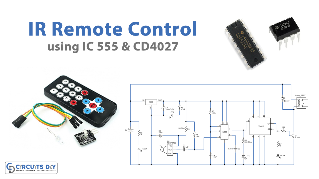
Circuit Diagram
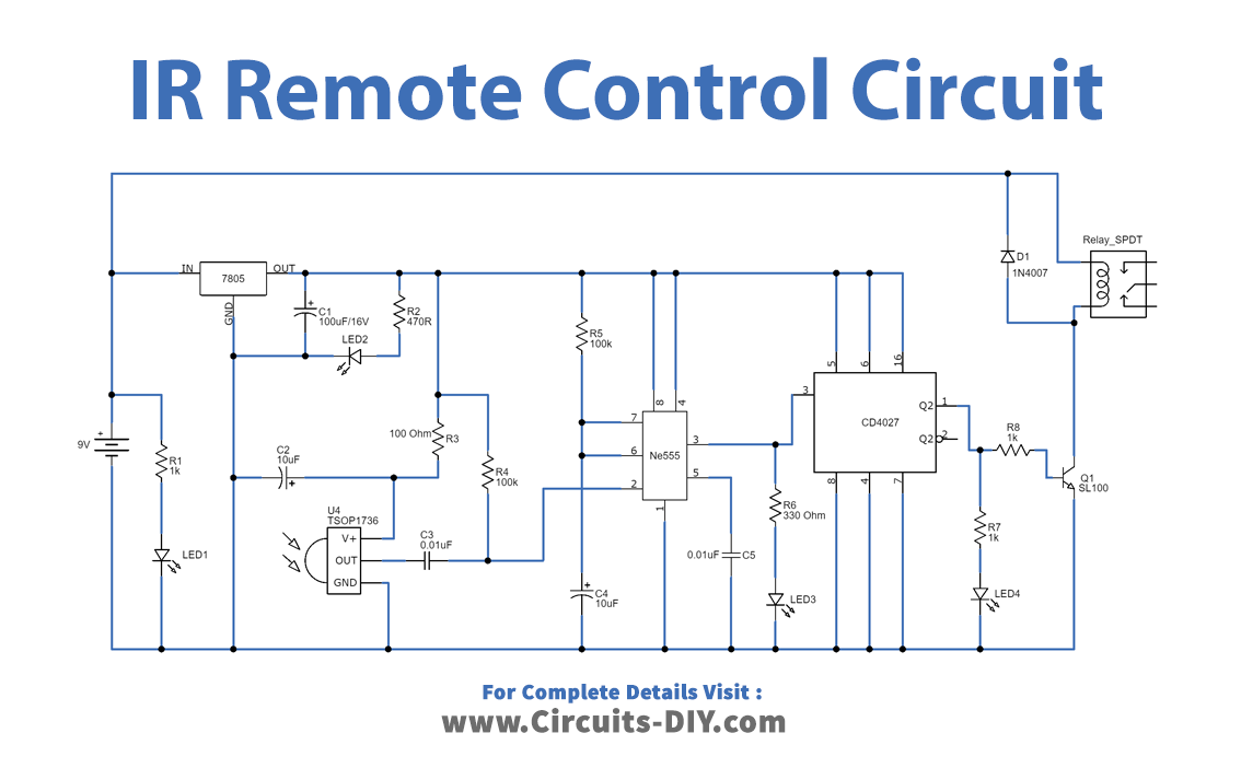
Working Explanation
As we can see in the circuit, the timer IC555 and decade counter IC CD4027 is the main part. Here the IR sensor TSOP1736 is used to receive IR rays from the remote control, and the SPDT relay act as an electro-mechanical switch to close and open the load circuit with the power supply. 9V DC supply is used to power this circuit, this supply is directly given to the relay and in another way regulated as 5V by using positive regulator IC 7805. The regulated 5V supply is given to the timer IC and counters IC.
Now when the IR rays fall on the sensor (TSOP1736,) it will produce a spike signal at 36KHz. This signal act as a trigger signal for timer IC, by this trigger input timer IC, will produce pulse output at the pin3. This pulse duration and duty cycle can be varied by varying R5 and C4 components. The output pulse from the timer IC should be at least 1-second duration. Further, this pulse output is given to the decade counter, hence the counter IC produces set to output at pin1. This will turn on the Q1 transistor, hence relay connects the load to the power supply.
If the IR rays are received by the IR sensor during the counter output as Set condition, the above-all operation continues but the counter output is turned to Reset. Hence the transistor Q1 turns off so the relay disconnects the load from the power supply.
Applications
Can be used to turn on or off electronic devices like TVs, radios, and washing machines.