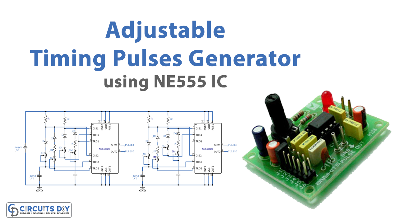
In this tutorial, we are making an Adjustable timing pulse generator circuit. The circuit looks a little complicated but if you follow this tutorial it will be easier to make and understand. We have used two 556 ICs. A 556 IC is a dual timer IC that has two 555 timers built in a single monolithic chip therefore it can provide pulses and oscillations at the same time.
Hardware Components
The following components are required to make Pulses Generator Circuit
| S.no | Component | Value | Qty |
|---|---|---|---|
| 1. | Input Supply DC | 5-16V | 1 |
| 2. | IC | NE556 Timer | 2 |
| 3. | Diode | 1N4148 | 8 |
| 4. | Variable Resistor | 5M | 8 |
| 5. | Electrolytic Capacitor | 220µF | 4 |
| 6. | Ceramic Capacitor | 10nF | 4 |
| 7. | Resistor | 1KΩ | 8 |
NE556 IC Pinout
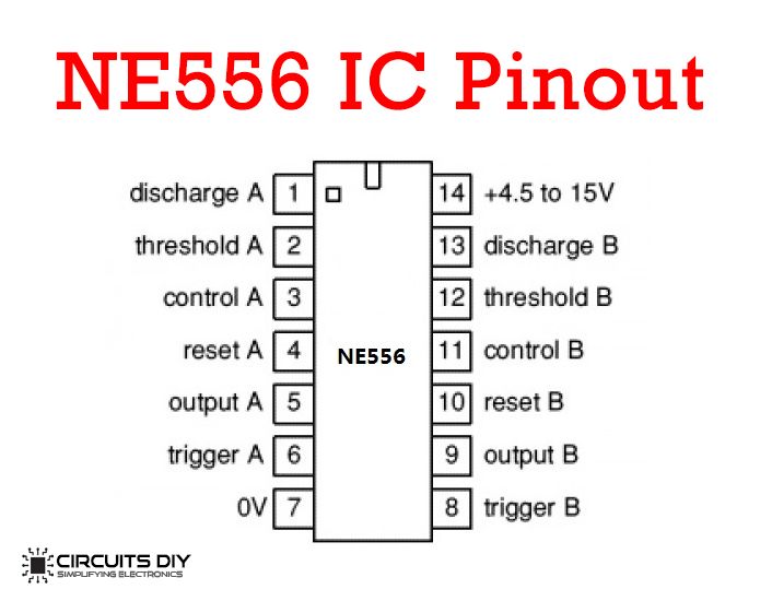
For a detailed description of pinout, dimension features, and specifications download the datasheet of NE556 IC
Pulses Generator Circuit

Working Explanation
The operating voltage of this circuit is 5 to 16 volts DC. This circuit is providing four different positive pulses and they repeat with different time frequencies and widths. When the circuit is activated both the ICs will start producing pulses from the four outputs of the circuit made as Pulse 1 till Pulse 4. There are 8 variable resistors used to adjust the ON and OFF time period of each pulse. Pulse 1’s ON time is adjusted by VR1 and OFF time is adjusted by VR2, the same goes for Pulse 2, Pulse 3, and Pulse 4, each pulse has two separate variable resistors for both ON and OFF time adjustments. This timing can be further increased or decreased by increasing or decreasing the value of the capacitors C1 to C4. The diodes D1-D8 used in this circuit are 1N4148.