Bird sound generator, as its name, suggests, outputs the chirping sound of birds. This electronic bird chirping circuit, an inspiration from mother nature is common and serves its purpose in toys, wall clocks, automobiles, alarms, and doorbells. This circuit involves just the two NE555 timer IC and a combination of resistor and capacitor bank.

Hardware Components
The following components are required to make Bird Sound Generator Circuit
| S.no | Component | Value | Qty |
|---|---|---|---|
| 1. | Breadboard | – | 1 |
| 2. | Battery | 9v | 1 |
| 3. | Connecting wires | – | 1 |
| 4. | IC | NE555 Timer | 2 |
| 5. | Speaker | 8Ω | 1 |
| 6. | Resistor | 100Ω, 15KΩ, 27KΩ, 30KΩ | 2,2,2,2 |
| 7. | Capacitor | 10µF, 47µF, 1000µF | 1,1,1 |
555 Timer Pinout

For a detailed description of pinout, dimension features, and specifications download the datasheet of 555 Timer
Bird Sound Generator Circuit
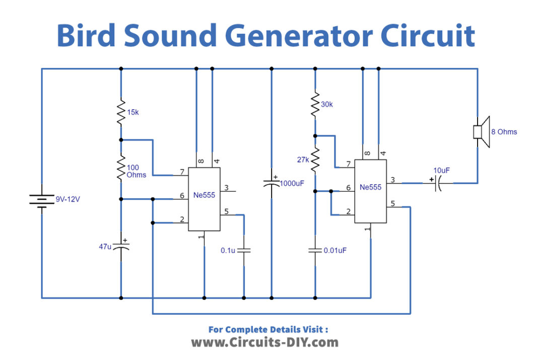
Working Explanation
The above circuit operates at 9V to 12V DC power supply. The two ICs work in their Astable mode of operation and the output of one functions as the input of the other. When working in Astable multivibrator mode, the oscillation is such that they produce alternate high and low pulses. Both the ICs IC1 and IC2 are responsible for controlling the tone of oscillations and switching oscillations, respectively.
In IC1 the two pins the trigger PIN 02 and the threshold PIN 06 are connected together. The output of IC1 is controlled by the voltage PIN 05. Additionally, controlling the output of the IC1 controls the output of the IC2. An 8Ω 1-2W speaker outputs the birds chirping sound. Moreover, the audio output of this circuit is already loud enough and, thus, amplification is not necessary.