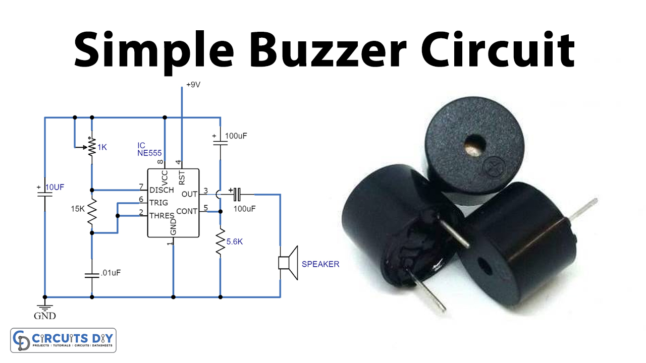
A Buzzer Circuit here is a sound producer with simple circuitry involving NE555 timer IC along with a variable resistor-capacitor network and a speaker.

Hardware Components
The following components are required to make Buzzer Circuit
| S.no | Component | Value | Qty |
|---|---|---|---|
| 1. | Breadboard | – | 1 |
| 2. | Connecting Wires | – | 1 |
| 3. | Battery | 9v | 1 |
| 4. | IC | NE555 Timer | 1 |
| 5. | Variable Resistor | 1k | 1 |
| 6. | Resistor | 15k, 5.6k | 1,1 |
| 7. | Electrolyte Capacitor | 10uF,100uF | 1, 2 |
| 8. | Speaker | 8 ohm | 1 |
| 9. | Ceramic Capacitor | 0.1uF | 1 |
NE555 IC Pinout

For a detailed description of pinout, dimension features, and specifications download the datasheet of 555 Timer
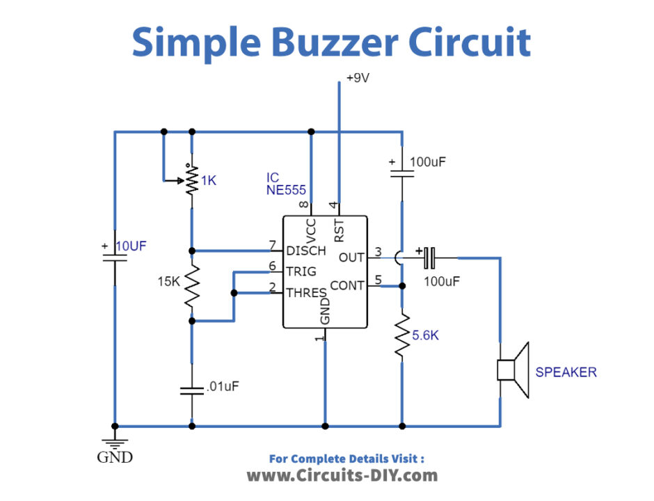
Buzzer Circuit
Working Explanation
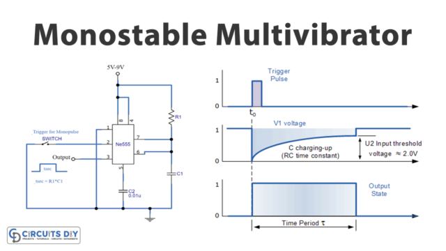
A NE555 IC produces accurate oscillation or time delays. Moreover, the interval timings can be controlled or set by using a resistor and capacitor network in the mono-stable mode of operation. Furthermore, the stable mode of operation of the IC involves the changing of frequency and duty cycles with the help of a capacitor and a variable resistor network.
The Circuit with all of the values of its resistor and capacitors set, when supplied with 9 Volts of battery, produces a buzzer sound. This IC NE555 drives an 8Ω to 25Ω loudspeaker to produce an audible square-wave tone. In addition to this, a Siren or 555 tone generator can be interchangeably used as a buzzer.
Application
- Used in small applications such as schools, Colleges, or any institution as Quiz buzzers.
- Used in a warning Siren application.