Vehicle turning indicators are very crucial while taking a U-turn or any roundabout. It would seem like a Simple LED Blinking. Be that as it may, it’s not just primary squinting LEDs inside indicators of vehicles.
We are building an extravagant Car/Bike Turning Indicator Circuit utilizing 555 Timer IC, with four LEDs. However, we can likewise control the speed or frequency of this LED indicator by essentially changing the value of the Potentiometer.
Hardware Component
The following components are required to make Signal Indicator Circuit
| S.no | Component | Value | Qty |
|---|---|---|---|
| 1. | IC | NE555 Timer | 1 |
| 2. | Resistor | 1K, 68K, 10K | 1, 1, 6 |
| 3. | Variable Resistor | 10K | 1 |
| 4. | Capacitor | 10uF, 470uF | 1 |
| 5. | Bread Board | – | 1 |
| 6. | Connecting wires | – | 1 |
| 7. | Diode | 1N4148 | 6 |
| 8. | LED | – | 4 |
| 9. | Battery | 9V | 1 |
| 10. | Transistor | BC547 | 4 |
| 11. | Power Supply | – | 1 |
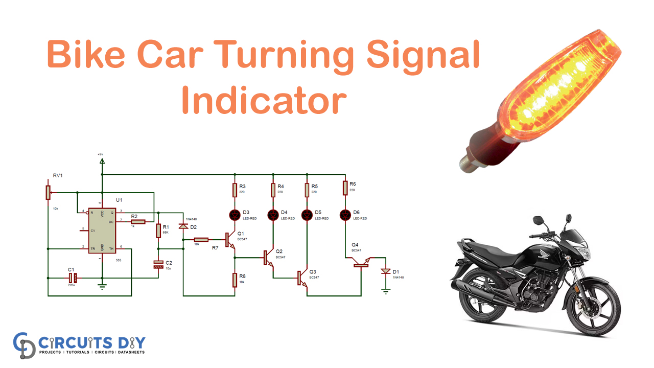
Signal Indicator Circuit
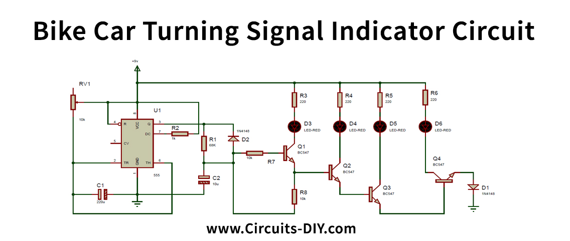
Working Explanation
The working operation of this Bike/car turning indicator is simple. The above circuit schematics are shown in the circuit connections. In this Bike Turning Signal Indicator circuit, we have used one 10K and 1K resistors and a capacitor for creating a delay. However, the 1N4148 diode is associated with reverse bias at the 555 timer IC yield pin to maintain a stable current. Because of the base current of the BC547/MPS42A (NPN) Transistor drive, the LEDs will turn ON and OFF. LEDs are associated with the semiconductor through a 220ohm resistor concerning Vcc. This 220ohm resistor will spare LED to may get harmed.
Applications and Uses
- Uses as a bike or car turning indicators
- It likewise utilizes knight rider LED circuits.