

This is an intriguing DIY circuit named TV remote jammer circuit that interferes with the IR receiver present in the TV by delivering a steady signal which meddles with the remote-control signal.
The key innovation employs in TV remotes is infrared light. Fundamentally, the TV remote emits a series of pulses when you press a button on the TV remote. IR transmitter is fixed to the outside of the TV remote. This IR transmitter emits pulses in some unique patterns for each button press. IR receiver, which is already organized on the TV, gets these sets of pulses, transmits by the TV remote, and recognizes which button is supposed to press in the TV remote.
The innovation behind the TV remote control jammer is producing a steady IR pulse with the transmitter’s carrier frequency. Consequently, a recognizable signal from the receiver object receives, and subsequently no action will be made. As a result, the circuit will obstruct your TV remote completely.
Hardware Required
| S.no | Component | Value | Qty |
|---|---|---|---|
| 1. | IC | NE555 Timer | 1 |
| 2. | PNP Transistor | 2N4403 | 1 |
| 3. | Diodes | 1N4148 | 2 |
| 4. | Ceramic Capacitors | 0.01µF | 2 |
| 5. | Resistor | 1KΩ, 160R, 560R | 1, 1, 2 |
| 6. | Variable Resistors | 20KΩ | 1 |
| 7. | IR LED | – | 2 |
| 8. | Battery | 9V | 1 |
NE555 Timer Pinout

| Pin No | Pin Name | Description |
|---|---|---|
| 1 | GND | Ground Pin |
| 2 | TRIGGER | Trigger Pin |
| 3 | OUT | Output Pin |
| 4 | RESET | Reset Pin |
| 5 | CNTRL | Control Pin |
| 6 | THRESHOLD | Threshold Pin |
| 7 | DISCHARGE | Discharge Pin |
| 8 | VCC | Voltage Common Collector |
Circuit Diagram
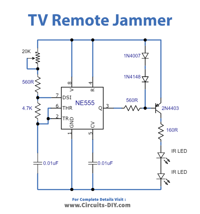
Circuit Operation
The circuit intends to deliver a 38 kHz signal. The fundamental component in this circuit is the 555 Timer IC. Here, it operates as an astable multivibrator IC.
The output of the 555 timer IC is additionally amplified with a 2N4403 PNP transistor to drive the infrared LEDs. It creates square pulses in the Range of 32 kHz – 40 kHz and can be differed by utilizing variable resistors. Most TV set uses 38 kHz recurrence frequency for TV Remote communication and delivering the only carrier at 38 kHz by utilizing this circuit will redirect the TV set from accepting the TV Remote signal. In the wake of building the circuit initially modify it for 38KHz by gradually changing the 20K variable resistors while working your TV remote and stop on where your TV remote will quit working. For good results fit the circuit in an appropriate enclosure with a 9V battery. The IR LEDs ought to be placed outside by making holes in the enclosure.
Applications and Uses
- We can utilize this circuit to stick the remote signals with the goal that the others can’t change the channel while viewing our preferred program on TV
- It won’t influence the signal-accepting limit of the TV


How can I order some of these circuits, boards or parts?