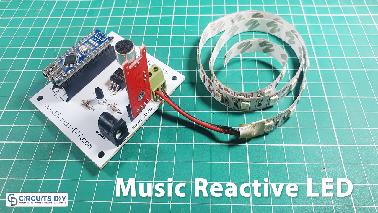
Are you getting bored while making intense electronic projects and do you want to make yourself relaxed by making some fun projects? We are here for you with some interesting projects of music-reactive LED strips.
A music-reactive LED circuit is a simple electronic circuit that responds to varying sound levels, usually, of the rhythmic melody from nearby playing music, and displays the changing intensity level of the sound signal in the form of blinking LEDs. It is a common circuit usually used for decorative purposes in places such as ceremonies, clubs & advertisements, etc. So Here we design “Music Reactive LED” using Arduino Nano Microcontroller.

PCBWay commits to meeting the needs of its customers from different industries in terms of quality, delivery, cost-effectiveness, and any other demanding requests. As one of the most experienced PCB manufacturers in China. PCBWay gives diverse options for customers to design their own PCBs. For example, more options for solder masks like red, yellow, blue, purple, pink, orange and transparent, and so on. They also have mature mechanisms of return or refund if any problem is caused by PCBWay.

- So Visit their website first -> PCBWay.com
- Register / Signup for New Account
- Upload your Gerber files
- Select Specifications like Quantity, Color, Dimensions &, etc
- Finally, Place your Order
Hardware Components
| S.no | Component | Value | Qty |
|---|---|---|---|
| 1. | Arduino | Nano | 1 |
| 2. | USB Cable Type A to B | – | 1 |
| 3. | PCB Board | – | 1 |
| 4. | Female Header | – | 3 |
| 5. | LED Strip | – | 1 |
| 6. | Screw Terminal Block | – | 1 |
| 7. | Sound Sensor | – | 1 |
| 8. | MOSFET | IRFZ44N | 1 |
| 9. | Transistor | – | 1 |
| 10. | Resistor | 10K | 2 |
| 11. | Battery | 9v | 1 |
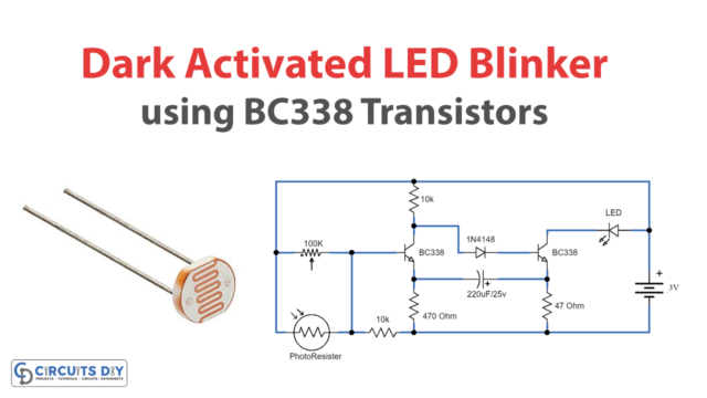
Circuit Diagram

Arduino Code
//Circuits DIY
//Sound Reactive Light
int soundSensor = 8;  //define Sound Sensor Pin
int LED = 9;          //define LED Strip Pin

void setup()
{
  pinMode (soundSensor, INPUT); //define Sound Sensor as input
  pinMode (LED, OUTPUT);        //define LED Strip as output
}

void loop()
{
  int statusSensor = digitalRead (soundSensor);   //define variable of the Sound Sensor status
                                                  //and read value of the Sensor's
  if (statusSensor == 1)        //When the Sensor detects a signal
  {
    digitalWrite(LED, HIGH);    //LED Strip will be active
  }
  else                          //If no signal is detected
  {
    digitalWrite(LED, LOW);     //The status of the LED strip is deactivated
  }
}
Explanation
The working of this circuit is pretty simple. An AC audio Signal is taken as input by the KY – 038 sound sensor module. The module feeds the analog out at pin A0 of the controller & the digital out to pin D8 of the micro-controller. Now to the working of the controller, D8 is defined as the sound sensor input while D9 is defined as the LED strip out using the pinMode() command. Now, using the digitalRead() command, each time the sound sensor detects a sound (status sensor == 1) it sets the pin D9 of the controller to high using DigitalWrite().
When D9 is set to high, the outDC signal acts as a control signal to the base of the BC547 transistor. The collector output of the transistor goes to the Gate of the IRFZ44N transistor. IRFZ44N is known for its high drain current and low switching time. It also has a low Rds value which will help in increasing the efficiency of switching circuits. The Drain output of the transistor then triggers the LED strip corresponding to the input sound signal.