All of us use tube lights in our houses. But only a beginner or an enthusiast in electronics would study its connections and operation. If you are such an enthusiast, we want to simplify your job. In this tutorial, we will make a “Tube Light connection diagram.”
You are probably aware that the tube light is a low-pressure mercury vapor gas discharge lamp that generates white light via fluorescent. Additionally, you should be aware that just a small number of wire points are required to connect a tube light. Let’s continue reading this post to learn more about the tube light connection diagram appropriate for the typical form of fluorescent tube light, shall we?
Hardware Required
| S.no | Component | Value | Qty |
|---|---|---|---|
| 1. | Fluorescent tube light | – | 1 |
| 2. | Electronic Ballast | – | 1 |
| 3. | Switch | – | 1 |
Circuit Diagram
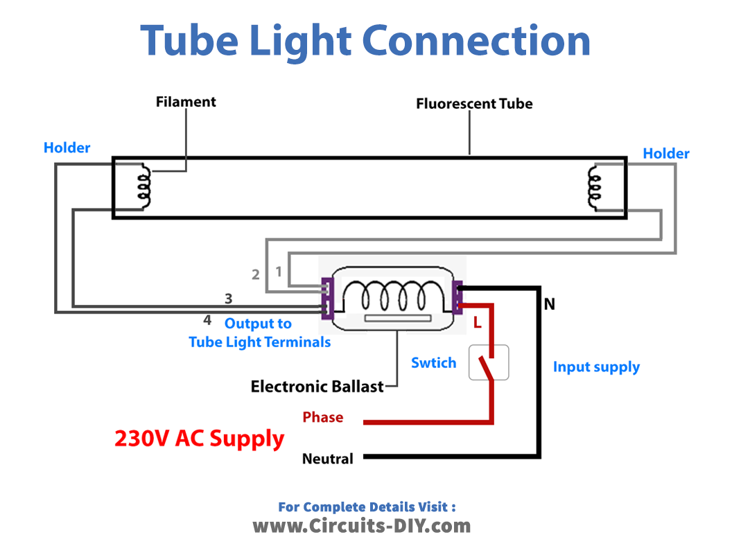
Working Explanation
Fluorescent light holders, ballasts, starters, and tubes are required for making electrical connections. There are two filaments and four terminals in a fluorescent tube; the starter is wired between the two, and the ballast is linked to the main AC supply and one of the filaments.
An AC supply is connected directly to the tube light’s other terminal, and a starter is used to ionize the mercury atoms in the tube light; after this process is complete, the starter is no longer necessary. The ballast changes the AC supply frequency to a higher frequency and regulates the power delivered to the fluorescent tube light.
Application and Uses
- Home, offices, and workplaces automation circuits.