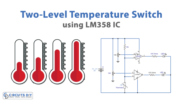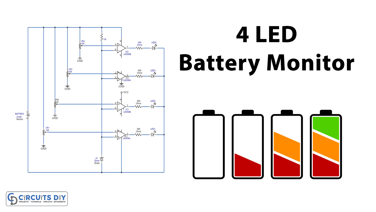
In this tutorial, we are making a 4 LED Battery Monitor Using Two LM358 ICs. This circuit is inexpensive and can monitor the battery voltage of batteries ranging from 6 to 24V. Each LM358 IC has two operational amplifiers, so there is a total of four op-amps in this circuit. An LED is connected with each op-amp for visual indication.
Hardware Components
The following components are required to make LED Battery Monitor Circuit
| S.no | Component | Value | Quantity |
|---|---|---|---|
| 1. | Battery | 6-12V | 1 |
| 2. | Op-amp IC | LM358 | 2 |
| 3. | LED | – | 4 |
| 4. | Resistor | 10K, 680Ω | 1, 4 |
| 5. | Variable Resistor | 10K | 4 |
| 6. | Zener Diode | 3V | 1 |
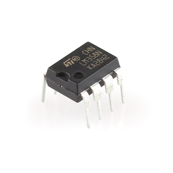
LM358 Pinout

For a detailed description of pinout, dimension features, and specifications download the datasheet of LM358
LED Battery Monitor Circuit
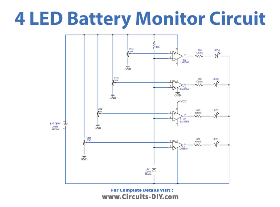
Working Explanation
The four op-amps in both ICs are working as a voltage comparator in this circuit. They detect the voltage of the battery under monitoring. Each op-amp has a variable resistor connected to its input to set the desired voltage to detect. When the comparator detects the voltage it activates the LED on the desired voltage.
Circuit Adjustments
Before using this circuit you need to make the following adjustments initially.
- If you are using a 12V battery then take an adjustable power supply and set its output voltage to 23.5V.
- Now replace the battery with this power supply in the circuit.
- Start adjusting the variable resistor VR1 until LED turns off.
- Now set the voltage on the adjustable power supply to 12.3V.
- Adjust the variable resistor VR2 slightly until LED turns off.
- change the voltage to 12.1V in the power supply and adjust the VR3 until LED 3 goes off.
- Again change the voltage to 11.9V and adjust the VR4 this time until LED 4 goes off.
- After these adjustments do a final check by increasing the voltage of the adjustable power supply to 12.6V and slightly down to 11.9V. At this point, all the LEDs will go off one by one on their preset voltages.
- When you are done with these settings and voltages are set, apply some glue to the variable resistors to fix them on their voltages.
The same procedure can be repeated for other batteries and the circuit should be adjusted according to battery voltage.