In this tutorial, we are making a project on a moisture-level LED meter circuit. This circuit senses and measures humidity or moisture levels in plants, wood, floor, soil, wall, etc. you can buy different moisture detectors from the market but if you are someone who likes experimenting with electronics then you should definitely try this circuit. It is an easy and inexpensive circuit as it is using one transistor, four pairs of resistors and LEDs, a few diodes, and probes.
The transistor used in this circuit is BC547. It is an NPN transistor that is acting as a switch for this circuit. The four LEDs will light up according to the moisture level i.e., low, medium, high, and full.
Hardware Components
The following components are required to make Moisture Level LED Circuit
| S.no | Component | Value | Qty |
|---|---|---|---|
| 1. | Battery | 12V | 1 |
| 2. | Probes | – | 2 |
| 3. | Transistor | BC547 | 1 |
| 4. | Resistor | 1K, 680Ω | 2, 2 |
| 5. | Variable Resistor | 100K | |
| 6. | Zener diode | 3.3V | 2 |
| 7. | Diode | 1N4148 | 6 |
| 8. | LED | – | 4 |
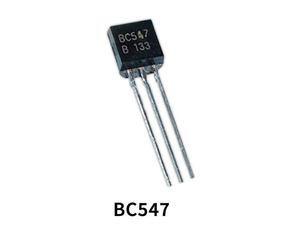
BC547 Pinout

For a detailed description of pinout, dimension features, and specifications download the datasheet of BC547
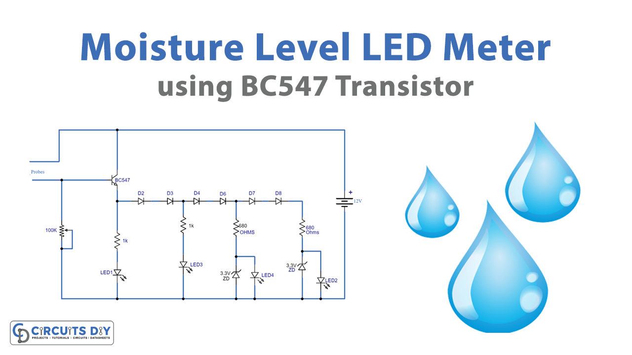
Moisture Level LED Circuit

Working Explanation
This circuit can be operated at 9V or 12V DC. We are using a 12V DC input supply in this circuit. Probes are used to detect the moisture level. When probes are placed on the material whose moisture is to be detected it will sense the presence of the moisture. Since water is a good conductor of electricity, the circuit will now start conducting and the transistor BC547 which is acting as a switch in this circuit will turn on. 6 1N4148 diodes are used in this circuit for the purpose of fast switching operation. So, when the moisture level is low LED 1 will glow, on the medium level LED 2 will glow, when moisture is at a high level LED 3 will glow, and finally when its full LED4 will glow. To adjust the sensitivity of this circuit we have used a variable resistor of 100KΩ
If you are going to operate this circuit at 9V then just remove the diode D5 and D6 and connect the 680Ω resistor near LED4 directly with D4. Make sure that you use LEDs from the same manufacturer, the same type so that it shows accurate results. LEDs of different manufacturers and types have different brightness so it can affect the accuracy of your circuit.
Applications and Uses
- Wall
- Plants
- Soil
- Wood