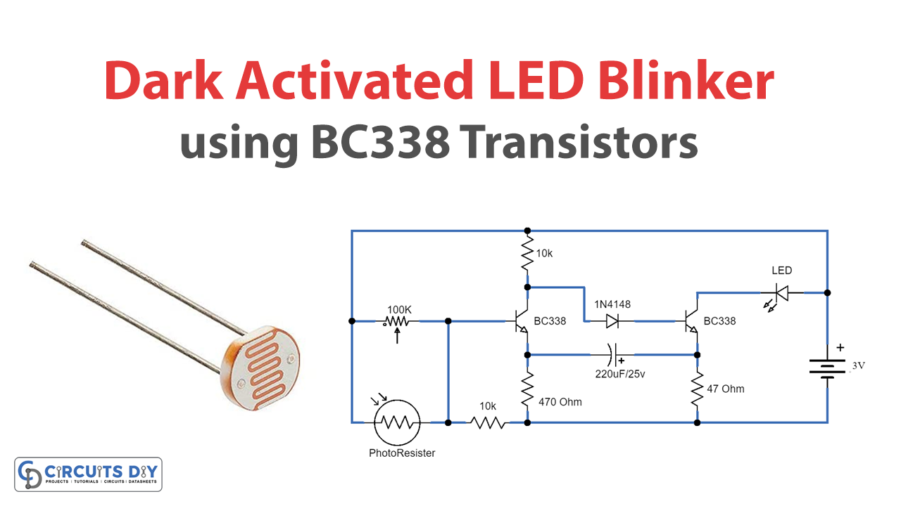
In this tutorial, we are going to make a circuit of dark-activated LED blinkers, the purpose of this circuit is to turn the LED ON when it gets dark. These circuits are really simple and have various applications in electronic projects as well as in our houses.
We are using an LDR in this project for sensing dark, it is a photoresistor that detects the presence of light. In full light the resistance of LDR is minimal and as the intensity of the light starts to decrease its resistance increases. In the dark, the resistance of LDR is a maximum of about 1 MEGA OHM. This is also called a variable resistor because its resistance varies according to the intensity of light.
Hardware Components
The following components are required to make a dark-activated LED Circuit
| S.no | Components | Value | Qty |
|---|---|---|---|
| 1. | Transistor | BC338 | 2 |
| 2. | LDR | – | 1 |
| 3. | Resistor | 10K, 47Ω, 470Ω | 2, 1, 1 |
| 4. | LED | – | 1 |
| 5. | Variable resistor | 100K | 1 |
| 6. | Electrolytic Capacitor | 220µF/25V | 1 |
| 7. | Battery | 3V | 1 |
| 8. | Diode | 1N4148 | 1 |
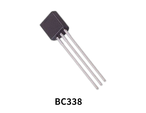
BC338 Pinout

For a detailed description of pinout, dimension features, and specifications download the datasheet of BC338
Dark Activated LED Circuit

Working Explanation
The operating voltage of this circuit is 3V. A variable resistor of 100K is used to adjust the blinking of the LED. When the light falls onto the photoresistor (LDR) its resistance will be minimal and all the voltage coming from the battery will be sent to the ground, and no power will be sent to the base of the transistor and it will remain switched OFF. When no light is present the resistance of the LDR will be maximized and less power will drop to the ground because the LDR holds it by high resistance and the transistor will get its sufficient voltage and switch ON which will turn ON the LED.
Applications and Uses
It can be used in houses to save energy by automatically switching the lights. It can be also used in Bedside Lamps or Emergency Lights.