In this DIY, we are going to develop a toggle switch. A toggle switch is utilized to flip the yield between two gadgets. It means when one device is ON, the second gadget stays OFF. And when the second gadget is OFF, the first gadget becomes ON. This flip of yield can be controlled utilizing a PUSH button switch so that you can control two devices using one catch.
Further, you can interface two Relays instead of LEDs to control the two AC machines. We have chiefly utilized 555 timer IC and the 4017 IC in this circuit. This project is easy to make and uses a few components.
Hardware Components
The following components are required to make Toggle Switch Circuit
| S.no | Component | Value | Qty |
|---|---|---|---|
| 1. | IC | CD4017 | 1 |
| 2. | IC | NE555 Timer | 1 |
| 3. | Resistor | 1k, 100k, 470 ohm | 1 |
| 4. | Electrolytic Capacitor | 1uF, 22uF | 1 |
| 5. | LEDs | – | 2 |
| 6. | Push Button switch | – | 1 |
| 7. | Power supply | 5-9v | 1 |
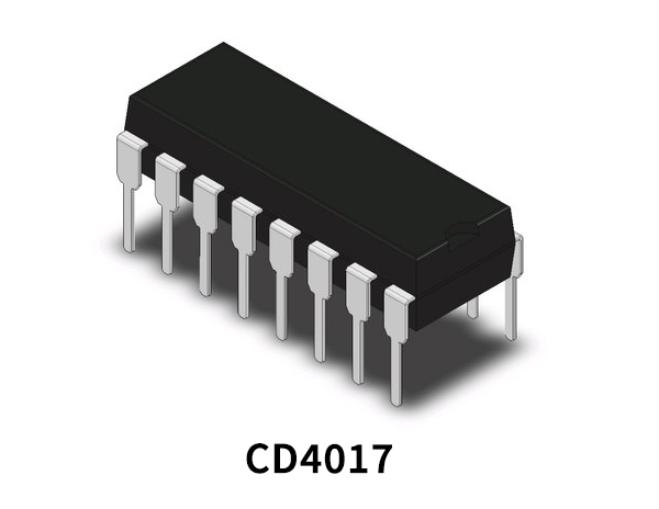
CD4017 Pinout
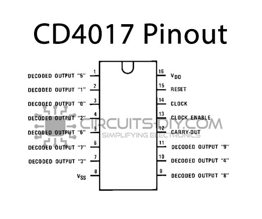
For a detailed description of pinout, dimension features, and specifications download the datasheet of CD4017
NE555 IC Pinout

For a detailed description of pinout, dimension features, and specifications download the datasheet of 555 Timer
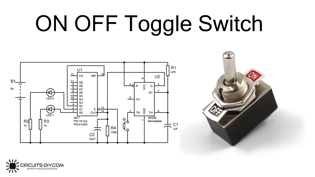
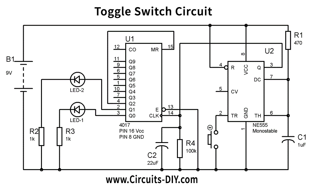
Toggle Switch Circuit
Working Explanation
4017 IC output advance with a positive edge clock pulse, so we have utilized 555 timer IC in Monostable mode to deliver a LOW to a HIGH clock pulse. We have associated a button on Trigger PIN 2 of 555 timer IC to provide a positive edge pulse with each button press. To trigger the 555 in monostable mode, trigger PIN 2 must be LOW, so we have associated it to the Ground utilizing the PUSH button switch. This created clock pulse at PIN 3 of 555 is given to 4017 IC at PIN 14.
When power is initially applied to IC 4017, the yield at PIN 3 (Q0) is HIGH, where we have associated FIRST LED. At the point when we press the PUSH button, at that point, a LOW to HIGH clock pulse is applied to PIN 14 of 4017, and the yield at Q0 turns out to be Low, and PIN 2(Q1) turns out to be HIGH, where we have associated Second LED.
Presently this position will stay until the following clock pulse. If we press the Push Button once more, the yield at Q1 becomes LOW, and Q2 turns out to be HIGH. What’s more, because Q2 is associated with the RESET pin 15 of 4017, it will reset the IC, and again yield at Q0 turns out to be HIGH, and Q2 turns out to be LOW. So it works like a toggle switch.
Applications and Uses
The toggle switch is widely used in
- home lighting and other applications