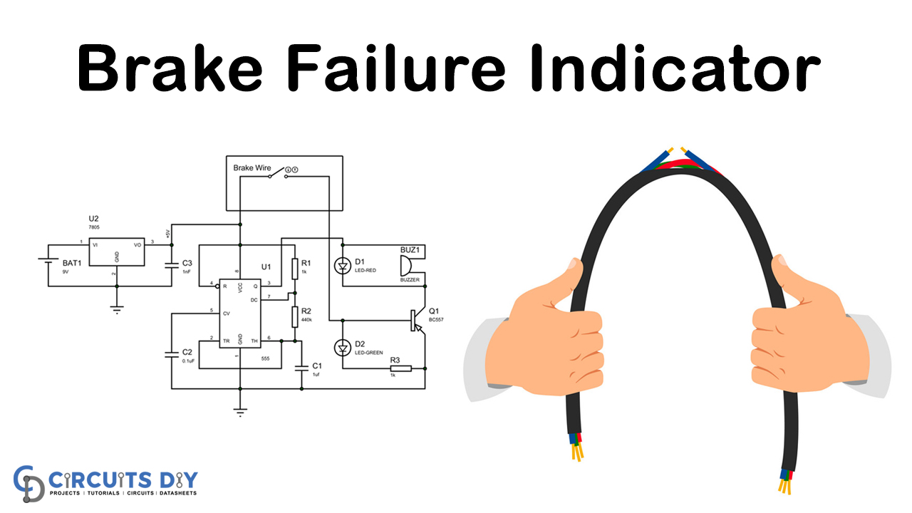
Most vehicles rely upon the “wire braking mechanism” to apply brakes to the vehicle. This system includes a Brake wire which runs from the brake switch to the “braking mechanism.” It is this wire that gets pulled when we apply brakes to stop our vehicle. After long use, these wires may get exhausted and get torn at a time, which will cause a brake disappointment.
So we will manufacture a circuit that will screen the progression of this wire; the circuit will light up a green shading LED if the system is fine, yet if the wire fails, the circuit will light up a red LED, additionally will signal a bell to alarm the driver.

Hardware Component
The following components are required to make Brake Failure Indicator Circuit
| S.no | Component | Value | Qty |
|---|---|---|---|
| 1. | PNP Transistor | BC557 | 1 |
| 2. | IC | NE555 timer | 1 |
| 3. | LED | Red and Green | 1 |
| 4. | Capacitor | 0.1uF, 1uF | 1, 1 |
| 5. | Buzzer | – | 1 |
| 6 | Breadboard | – | 1 |
| 7. | Voltage Regulator IC | 7805 | 1 |
| 8. | Resistor | 10KὨ, 440KὨ | 1, 1 |
NE555 IC Pinout

For a detailed description of pinout, dimension features, and specifications download the datasheet of 555 Timer
Brake Failure Indicator Circuit
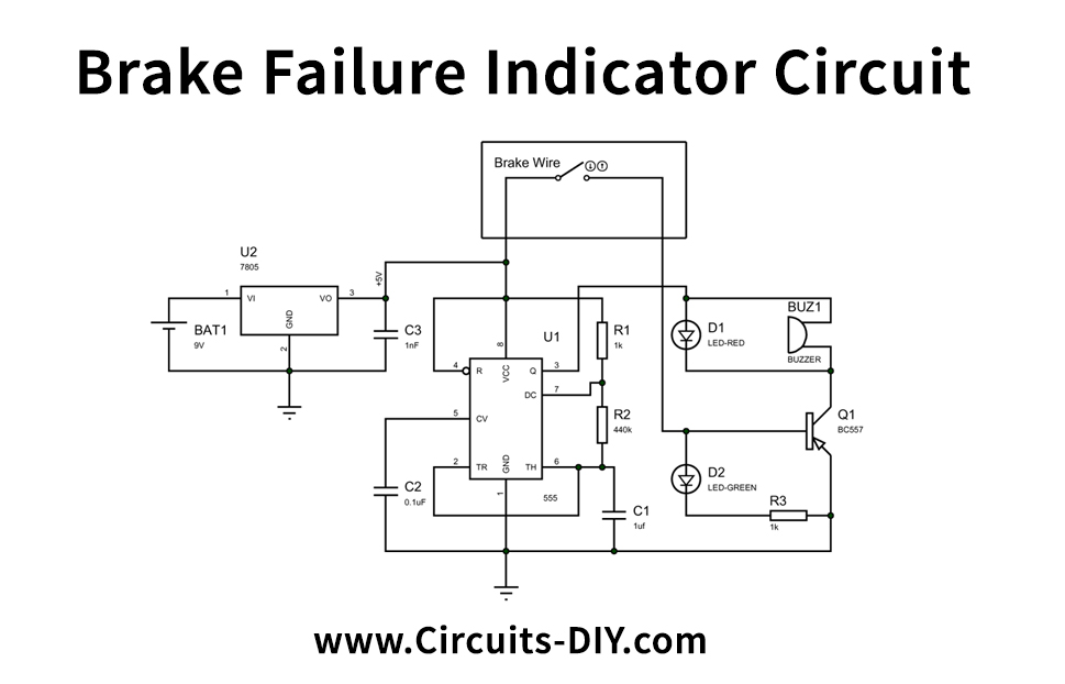
Circuit Operation
First, complete the association of the circuit, then power the circuit with a power source like a battery, and ensure the Brake cable. In this tutorial, we have utilized a typical green cable as a brake link. It is associated over the +5V and base of BC557 through a resistor that appeared in the circuit.
When everything is okay, and there is no damage to the brake so the green light will be lit up and buzzer, and the red light turn “OFF,” and when there is something wrong with your brake system, then the red LED and the buzzer will turn “ON.”
Applications and Uses
The application of this brake failure indicator circuit is to monitor the condition of the brake and give a signal through LED and buzzer if any damage happens.