Introduction
Electronic bongos are musical instruments that produce authentic bongo sounds when two touch plates are tapped. While synthesizers can be expensive, generating single sounds like bongos inexpensively is possible.
This article will explain how to build an electronic bongo circuit into a full-sized or small look-alike bongo drum.
Hardware Required
| S no | Components | Value | Qty |
|---|---|---|---|
| 1 | Transistor | BC548 / MPS-A18 | 2 |
| 2 | Resistor | 10K, 1M, 4K7, 330K, 47k | 6, 2, 2, 2, 4 |
| 3 | V. Resistor | 470R, 50k | 2, 1 |
| 4 | Polar Capacitor | 1u, 10u | 2, 1 |
| 5 | Non Polar Capacitor | 100n, 68n, 47n, 15n, 10n | 2, 1, 1, 2, 2 |
| 6 | Battery | 9V | 1 |
| 7 | Switch | 8 – 40R | 1 |
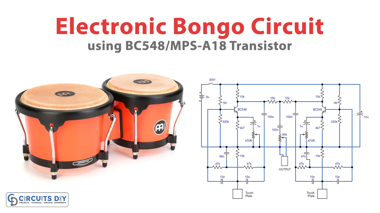
Circuit Diagram

Creating Touch Plates for Electronic Bongo Circuit
The touch plates for the electronic bongo circuit can be made of any electrically conductive material, such as copper, brass, stainless steel, aluminum, etc. They should be at least 50mm across but can be more extensive and any shape desired. The touch plates must be spaced away from any metal surface by at least 25mm if using a metal case.
Potentiometers for Electronic Bongo Circuit
Potentiometers RV1 and RV3 are used during the initial setup process and do not require quick accessibility. Potentiometer RV2 regulates the sound output level, and it is necessary if the unit is to drive an amplifier without any built-in volume control. This potentiometer can be disregarded through the board and replaced by a larger rotary potentiometer far from the circuit, requiring a 50k half-watt rotary device with a logarithmic curve.
Setting Up the Electronic Bongo Circuit
After connecting the unit to an appropriate amplifier and loudspeaker and turning on the amplifier with the volume control at a lower setting, turn RV1 to a minimum setting and RV2 to around the mid-way point. Transistor Q1 should now oscillate, and a sound should be heard from the loudspeaker. Adjust RV1 until the oscillation stops, and momentarily touch the connected touch plate. This will trigger the circuit to generate a bong sound that decays away. Continue to adjust RV1 until an authentic bongo sound is produced. Repeat the process for the second oscillator by changing RV3.
Testing the Electronic Bongo Circuit
After setting up the circuit, turn the amplifier up loud and play. The electronic bongo circuit can generate frequencies of approximately 290Hz and 400Hz, dependent upon C1, C2, C4, C9, C10, and C11. The frequency generated is inversely proportional to the values of these capacitors, so doubling their value will double the bong frequency. The circuit can also be modified to possess a whole series of oscillators with various frequencies.
How the Electronic Bongo Circuit Works
The electronic bongo circuit consists of two twin T-type sine wave oscillators, each practically equivalent. There is one oscillator per touch plate, each with a filter in the feedback loop. If the loop gain is more than unity, the circuit will oscillate. In this application, the gain is adjusted to be slightly lower than unity. Touching the touch plate initiates the oscillator, but oscillations will stop functioning when the finger is taken off the touch plate. The decay rate is a function of circuit gain directed by RV1 and RV3.
Final Words
In conclusion, the electronic bongo circuit provides a cost-effective and straightforward way to generate authentic bongo sounds. Hope you like the tutorial. Try this circuit, and for any query, feel free to comment; we would love to hear from you!