This is a tutorial for making a sensitive mic circuit that boosts faint sounds from distance. It is quite sensitive and provides good gain to weak audio signals. This circuit is small and straightforward to utilize since it uses only two transistors and some other passive components and it won’t cost you much.
For an inexpensive sound amplification process required in electronic projects, this circuit will be suitable. You can use a dynamic microphone, condenser microphone with an active circuit inside, or electret microphone that we are using in this project.
Hardware Components
The following components are required to make a Sensitive Microphone Circuit
| S.no | Component | Value | Qty |
|---|---|---|---|
| 1. | Battery | 9-12V | 1 |
| 2. | Electret Microphone | – | 1 |
| 3 | Resistor | 10K, 620K, 10K, 220K, 1.2K | 1, 1, 1, 1, 1 |
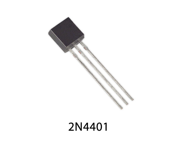
| 4. | Transistor | 2N4401 | 2 |
| 5. | Headphone | – | 1 |
| 6. | Variable Resistor | 20K | 1 |
| 7. | Ceramic Capacitor | 100nF | 2 |
| 8. | Electrolytic Capacitor | 1µF | 1 |
2N4401 Pinout
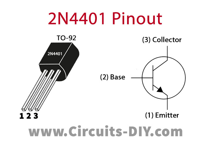
For a detailed description of pinout, dimension features, and specifications download the datasheet of 2N4401
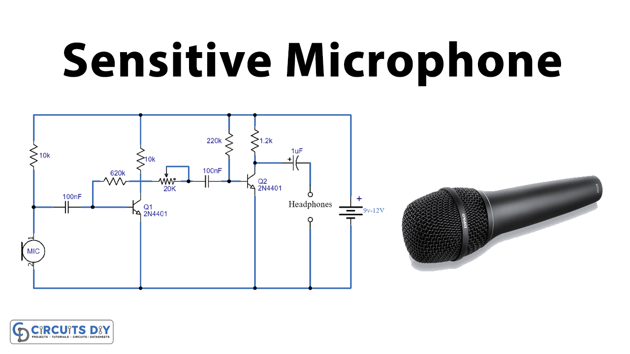
Sensitive Microphone Circuit

Working Explanation
This circuit is powered by a 9-12V battery. It is built around two NPN transistors Q1 and Q2 which are divided into two different stages. The first stage is a high gain mic preamp circuit and the second stage is a single transistor amplifier to drive the headphones.
Electret mic is used to send the audio signals in the circuit, these signals are weak therefore they are amplified on the first stage which is a preamp circuit. The output of the electret mic is combined by using a capacitor of 100nF, this capacitor helps in eliminating the DC material in the audio transmission. A 10K resistor is used to offer the necessary biasing to the microphone.
Transistor Q1 is set up as an NPN transistor and is achieved through a 620K resistor which offers negative feedback for this transistor. There is a variable resistor of 20K to adjust the output of Q1, which is then fed to transistor Q2. The same process is done in the second stage and it provides additional amplification. A capacitor is used at the output of Q2 to block the DC voltage of the particular biasing of the second transistor. The amplified signal now is driven through headphones
Applications and Uses
- You use this circuit for audio sensing purposes
- It is also used for several programmed robotic receptors
- Used as a pre-amplifier for FM audio receivers