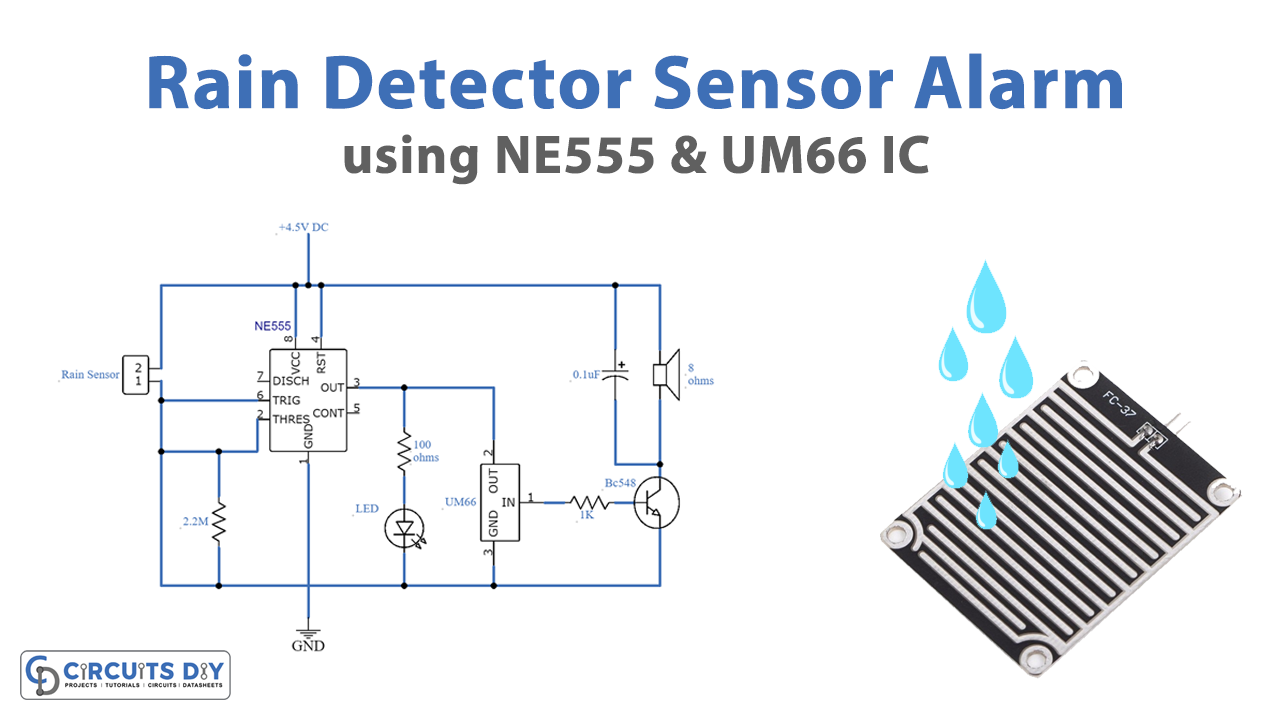
Today we are going to demonstrate a very interesting project of a 555 rain detector/sensor alarm circuit. This circuit will produce a melody when it detects any water drops on the surface. The circuit is working around two ICs.
One is a 555 timer IC that is providing oscillations and time delay to the circuit. Another IC is a UM66 melody generator IC that is building the melody circuit. A transistor amplifier is used at the output of this IC to amplify the audio output to drive the 8 ohms, Speaker. LED is used for visual indication of the presence of rain.

Hardware Components
| S.no | Component | Value | Quantity |
|---|---|---|---|
| 1. | Input Supply DC | 4.5V | 1 |
| 2. | Sensor | – | 1 |
| 3. | IC | NE555 timer | 1, 1 |
| 4. | LED | – | 1 |
| 5. | Transistor | BC548 | 1 |
| 6. | Resistor | 2.2M, 100ohms, 1K | 1, 1, 1 |
| 7. | Electrolytic Capacitor | 0.1uF | 1 |
| 8. | Speaker | 8 ohms | 1 |
| 9. | IC | UM66 | 1 |
NE555 IC Pinout

For a detailed description of pinout, dimension features, and specifications download the datasheet of 555 Timer
555 Rain Alarm Circuit
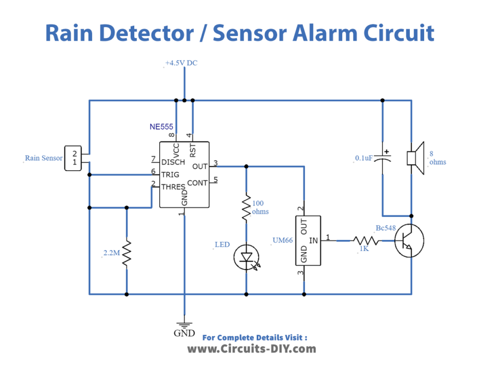
Working Explanation
This circuit is operated at 4.5 volts DC, The sensor used in this circuit is hand-built. It can be made by different techniques such as simply attaching thin wires on a 3 to 6 inches square plastic piece, there should be a 1-3 millimeter gap between all wires. When the sensor senses the rain it sends an input signal to the 555 timer IC which activates the LED and UM66 melody generator IC.
The output melody will be amplified by the transistor and drives the speaker. Current limiting resistors are used in this circuit to protect the components. If you are going to operate this circuit at high voltage like 6, 9, or 12 volts then a Zener diode of 3.3V along with a resistor will be required before the UM66 IC.