Introduction
Are you the one who forgets to turn OFF the motor after turning it ON? And are you worried about the wastage of water? Do you need a device that can control the water level or save water? So, why not make it by yourself!!! In this article, we are going to design and explore the water level controller. If you know when very little about electronics, you are in the right spot. Let’s start to unearth the solution to your problem.
The circuits typically need 555 timer IC, relays, LEDs, diodes, transistors, and motors. All these components have an active role in circuitry. Remember, that this project may not handle high power. Because components used in this are sensitive and can be damaged easily.
Hardware Required
| S. No | Components | Value | Qty |
|---|---|---|---|
| 1. | Breadboard | – | 1 |
| 2. | DC power supply | 12V | 1 |
| 3. | Timer IC | NE555 | 1 |
| 4. | NPN Transistor | BC546 | 4 |
| 5. | NPN Bipolar Transistor | PN2222 | 2 |
| 6. | LED | – | 3 |
| 7. | Resistors | 220 ohms, 1K, 2.2K, 4.7K, 10K, 100K | 2, 1, 3, 1, 2, 4 |
| 8. | Electrolytic Capacitor | 100uF, 2.2uF | 1, 1 |
| 9. | Ceramic Capacitor | 0.01uF | 1 |
| 10. | Diode | 1N4007 | 1 |
| 11. | Relay | – | 1 |
| 12. | Motor | – | 1 |
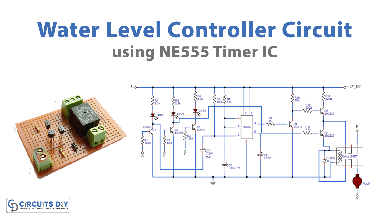
Circuit Diagram
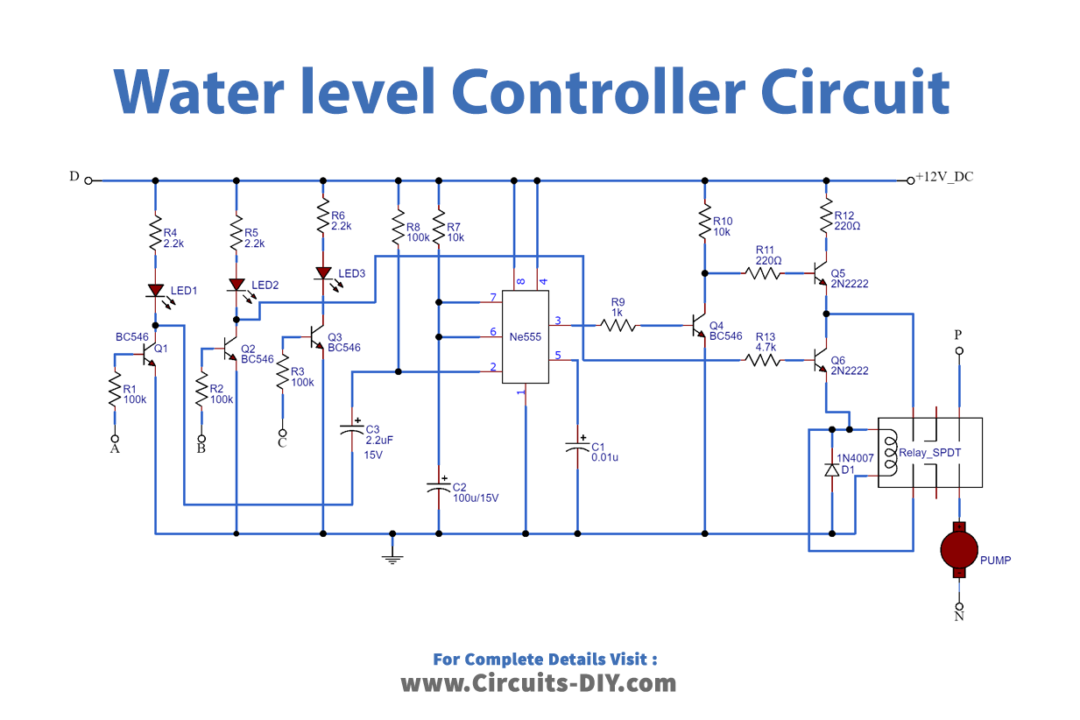
Working Explanation
Place point D wire at the bottom level of the tank. Point A wire should be placed at full level. Point B at the half and Point C wire at medium level. When the water level is below quarter-point A, B, and C will be open. However, the transistors Q1, Q2, and Q3 will remain OFF. The LEDs will get ON according to the level of water and the transistor’s state. The Collector of Q1 is connected to IC’s trigger pin. So, when water reaches the full level Q1 is turned On. Therefore collector gets onto the ground and triggers the IC. IC turns ON the Q4 which is already connected to the base of Q5. When Q5 gets OFF, the relay gets OFF and will remain OFF until the water reaches the medium point
Applications
- In-home automation
- Can control commercial centers
- For agricultural purposes
- Anywhere to control the water level