You must have known the importance of door alarms. They work by detecting if the gate is closed or open. There are alarms set in the refrigerator doors which produce sound when they are activated. In this electronic project, we are going to make a “Magnetic Door Alarm circuit using a 3144 Hall-effect Sensor“

Hardware Components
The following components are required to make Magnetic Door Alarm Circuit
| S.No | Component | Value | Qty |
|---|---|---|---|
| 1. | Breadboard | – | 1 |
| 2. | IC | NE555 Timer | 1 |
| 3. | Battery | 9v | 1 |
| 4. | Hall Effect Magnet Sensor IC | 3144 | 1 |
| 5. | Voltage Regulator IC | LM7805 | 1 |
| 6. | NPN Transistor | BC547 | 1 |
| 7. | Potentiometer | 50K | 1 |
| 8. | Resistors | 1k, 10k | 4,1 |
| 9. | Electrolytic Capacitor | 10uF | 1 |
| 10. | LED | 5mm | 1 |
| 11. | Buzzer | – | 1 |
555 IC Pinout

For a detailed description of pinout, dimension features, and specifications download the datasheet of 555 Timer
LM7805 Pinout
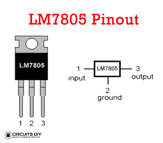
For a detailed description of pinout, dimension features, and specifications download the datasheet of LM7805
3134 Pinout
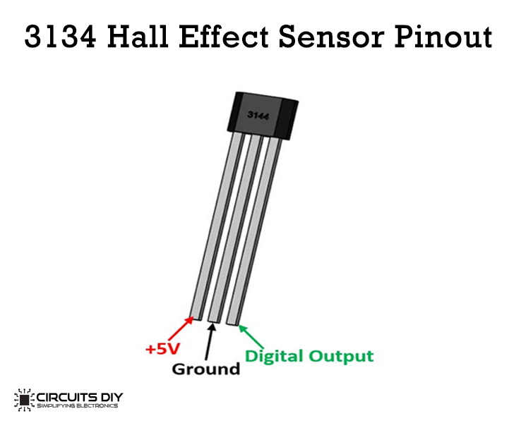
For a detailed description of pinout, dimension features, and specifications download the datasheet of 3134
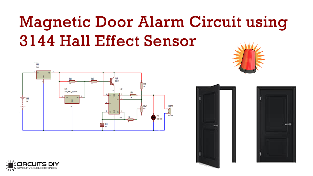
Magnetic Door Alarm Circuit
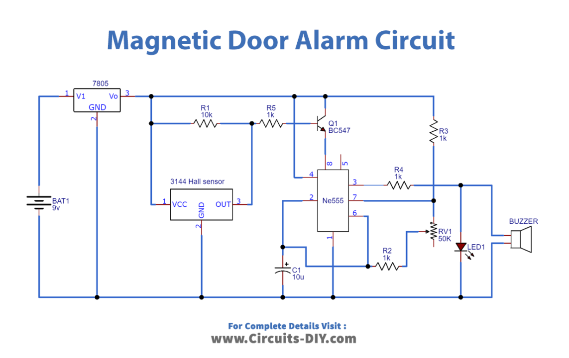
Working Explanation
The main component is a hall effect magnet sensor that works by sensing the magnet when it gets activated. Afterward, it produces signals based on the polarity of the magnet. This device works on the principle of the hall effect according to which, the voltage will be perpendicular to the current flowing through a semiconductor or a conductor.
Moreover, the door alarm also uses a 555 timer IC in an astable mode that works like an alarm. It is connected to the R1 resistor in between pin7 and Vcc. Another resistor R4 is connected between pins 7 and 6. The hall sensor detects the opening and closing of the door and the output is connected to the BC547 transistor.