A Knight rider circuit is a common electronic circuit, generally used for decorative purposes on automobiles, roadwork signs & Home decorations. The appeal of this circuit has remained constant for quite a long time. Usually, the behavior of a knight rider circuit is achieved by combining a clock circuit such as a timer or a stable multivibrator with a counter such as a decade counter. So, in this project, we will design a knight rider circuit using a CD4017 Decade counter with a stable multivibrator circuit.
A CD4017 IC is a 16-pin CMOS decade counter/Divider with 10 outputs. It is also known as the ‘Johnson 10 stage decade counter’. It has 10 decoded outputs that give output signals one by one in sequence when a clock signal from the clock input is given.
Hardware required
You will need the following parts to build this project
| S.no | Component | Value | Qty |
|---|---|---|---|
| 1. | Decade Counter | CD4017 | 1 |
| 2. | NPN Transistor | 2N4401 | 2 |
| 3. | PNP transistor | 2N4403 | 1 |
| 4. | LEDs | 6x | 6 |
| 5. | Diodes | 1N4148 | 11 |
| 6. | LEDs | 100K Pot | 1 |
| 7. | Capacitor | 47uF, 1uF | 11 |
| 8. | Resistor | 22K, 5.1K, 1K, 360Ohms | – |
| 9. | Battery | 9V | 1 |
| 10. | Battery Clips | – | 1 |
| 11. | Breadboard Connecting Wires | – |
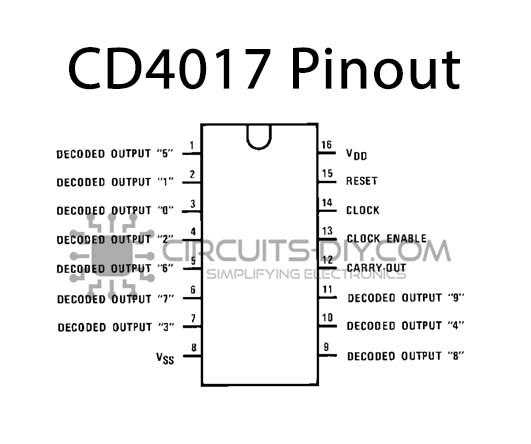
| Pin Name | Pin No. | Description |
|---|---|---|
| OUTPUT | 1-7 & 9-11 | pins to receive the output in a sequential manner. (Q0-Q9) |
| VSS | 8 | Ground Pin |
| CARRY OUT | 12 | To connect one or more CD4017 ICs. |
| CLK INHIBIT | 13 | It is used to switch the counter “on” and “off” |
| CLOCK | 14 | Whenever the CLK pin goes high, it provides the output. |
| RESET | 15 | It is used to reset the counter to zero. |
| VDD | 16 | Positive Voltage Supply pin to IC |
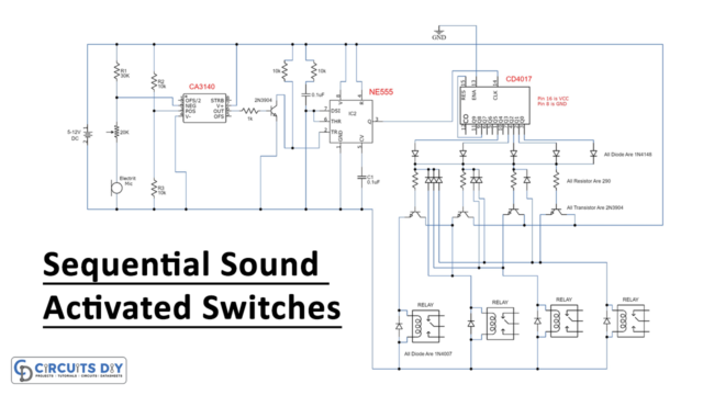
Circuit Diagram

Working Explanation
The heart of the circuit is a CD 4017 decade counter IC. The IC has 10 outputs. The IC will activate each of its outputs in a sequence manner each time a positive pulse receives on its clock pin 14. Here, an astable multivibrator circuit provides a positive clock input.
In this circuit, the outputs of the ICs are connected in a manner so it will show reverse forward running LEDs. The pulse frequency or the speed of the running LED can be increased or decreased with the 100K variable resistor. The circuit can run with a 5V to 12V DC power source. Use a lower value current limiting resistor in the place of 390 ohms when operating the circuit on low voltage. For example, if you are operating a circuit below 9V, then use a 290 ohms resistor.
Applications
- Usually serves decorative purposes on automobiles such as cars & bikes
- Also used for making construction and roadwork signs.