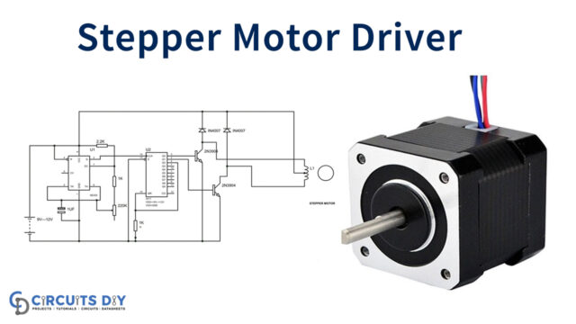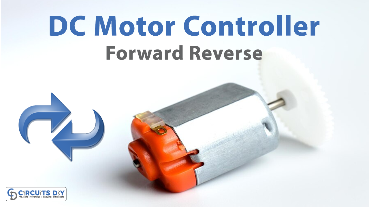
A DC motor controller is any device that can manipulate the position, speed, or torque of a DC-powered motor. There are controllers for brushed DC motors, brushless DC motors, as well as universal motors, and they all allow operators to set desired motor behavior even though their mechanisms for doing so differ. Here we design a forward reverse DC motor controller with timer IC and other easily available components.
Hardware Required
| S.no | Component | Value | Qty |
|---|---|---|---|
| 1. | IC | NE555 Timer | 1 |
| 2. | DC Motor | – | 1 |
| 3. | DPDT Switch | – | 1 |
| 4. | Transistor | BD139 | 1 |
| 5. | Diode | 1N4001 | 3 |
| 6. | Resistor | 1KΩ,33Ω | 1,1 |
| 7. | Variable Resistor | 50KΩ | 1 |
| 8. | Capacitor | 0.1uF,0.01uF | 1,1 |
| 9. | Connecting Wires | – | – |
| 10. | Battery | 12V | 1 |
Circuit Diagram
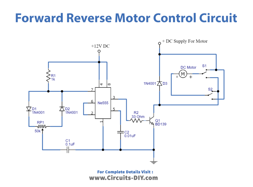
Working Explanation
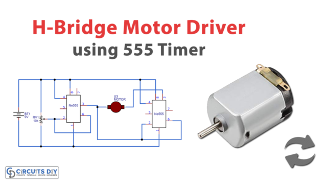
As we can see in the circuit, the DC motor is connected to the supply through DPDT (double pole double through) switch, we can get forward and reverse rotation from the motor by changing the switch position. Because this switch interchanges power supply polarity applied to the motor. Here the diode D1 protects the DC motor from the back emf effect, so there is no output load effect rise. The NPN transistor BD139 drives the output from the timer IC, this output pulse duration decides the speed of the DC motor. Now we can vary the pulse output of the timer by varying the VR1 resistor. The basic motive of this circuit is to meet the forward/reverse operation of the DC motor with speed control.
Applications
Some DC motors have unfit RPM (rotation per minute) for projects to control the speed of DC motors this simple circuit can be used.