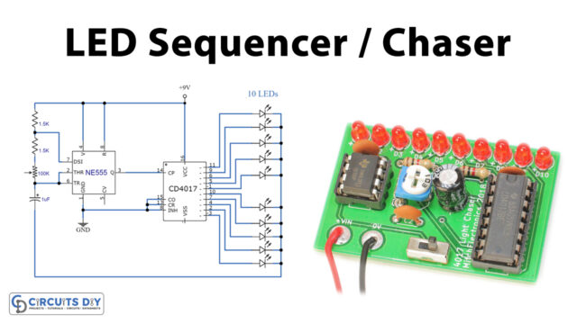
A Decade Binary Counter Circuit is theoretically a motor-driver circuit. The advantages of this circuit are that it can be used to operate 2-10-step stepper motors. Let’s talk about the fundamentals of the stepper motor before going any further.
The stepper motor does not operate on a constant power supply. Only regulated and ordered pulses of power can operate it. We have to discuss UNIPOLAR and BIPOLAR stepper motors before going any further. We may take the center tapping all the windings for a common terrain or a common power, as seen in a UNIPOLAR stepper motor.
Hardware Components
The following components are required to make Stepper Motor Driver Circuit
| S.no | Component | Value | Qty |
|---|---|---|---|
| 1. | IC | NE555 timer | 1 |
| 2. | Capacitor | 1µF, 100µF | 1 |
| 3. | Variable Resistor | 220K | 1 |
| 4.. | Resistor | 1K, 22K | 1 |
| 5. | Supply voltage | +9V to +12V | 1 |
| 6. | IC | CD4017 | 1 |
| 7. | Diode | 1N4007 | 1 |
| 8. | Transistor | 2N3904 or 2N2222 | 2 |
NE555 IC Pinout

For a detailed description of pinout, dimension features, and specifications download the datasheet of NE555 IC
CD4017 Pinout
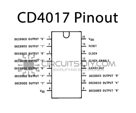
For a detailed description of pinout, dimension features, and specifications download the datasheet of CD4017
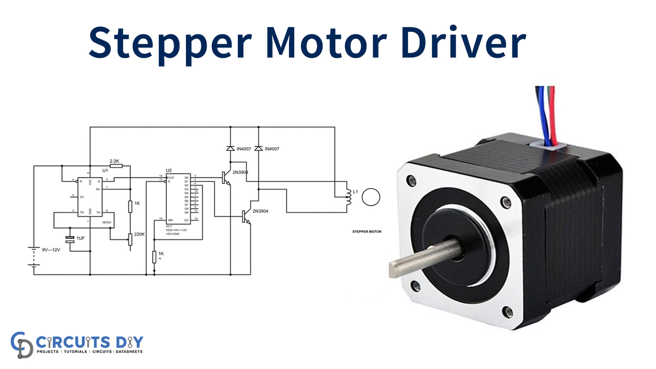
Stepper Motor Driver Circuit
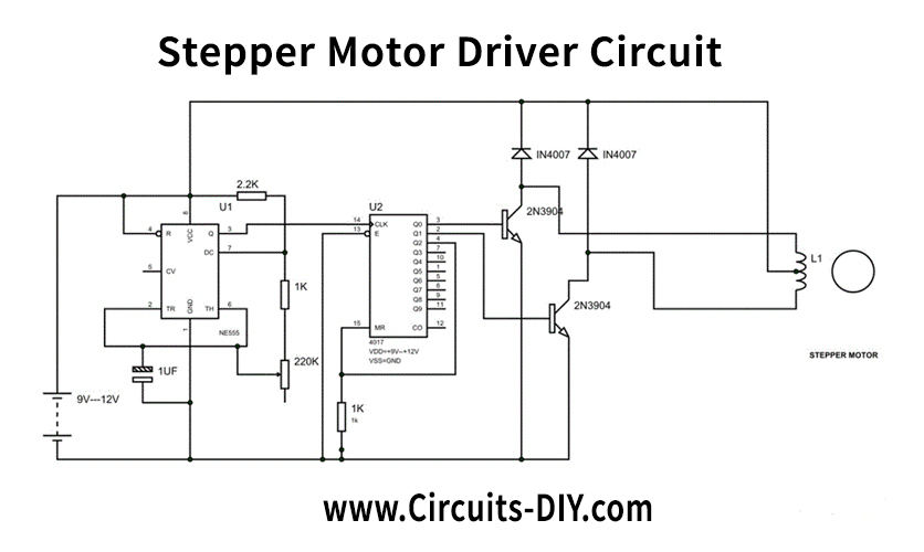
Circuit Operation
The figure displays the two-stage stepper-motor driver circuit diagram. The 555 timer IC now produces the clock or the square wave, as seen in the circuit diagram. In this case, the clock generation frequency can not be sustained continuously, so the step-motor must have variable rpm.
A pot or preset with a 1 K resistor in the branch between the 6th and 7th pins is paced to achieve this variable velocity. The resistance varies with the pot, so 555 changes in the branch produce the clock frequency.

In the figure, the important thing is only the third formula. You can see that the frequency is inversely related to R2, which is 1 K+220 K POT in the circuit. Thus the increase in R2 causes a reduction in frequency. And then, the frequency decreases if the pot is changed to boost the branch resistance.
DECADE BINARY counter is supplied with the clock created by the 555 timer IC. The binary counter now counts the number of pulses fed at the clock and makes a high pin output for the respective pin. If the count for events is 2, then the counter pin Q1 becomes high, and the count pin Q5 is high if 6 is counted. This is equivalent to a binary counter, except the count is decimal, i.e., 1 2 3 4 — 9, so only Q6 pins would be high if the count is 7. (1 + 2 + 4) Pins are strong in binary counters Q0, Q1, and Q2. These outputs are supplied to transistors to operate the stepper motor better.
Applications and Uses
Since the stepper motor is controlled digitally using an input pulse, it can be run on computer-controlled systems. They are used in machine tool numerical control and used for tape players, discs, printers, and electric watches.