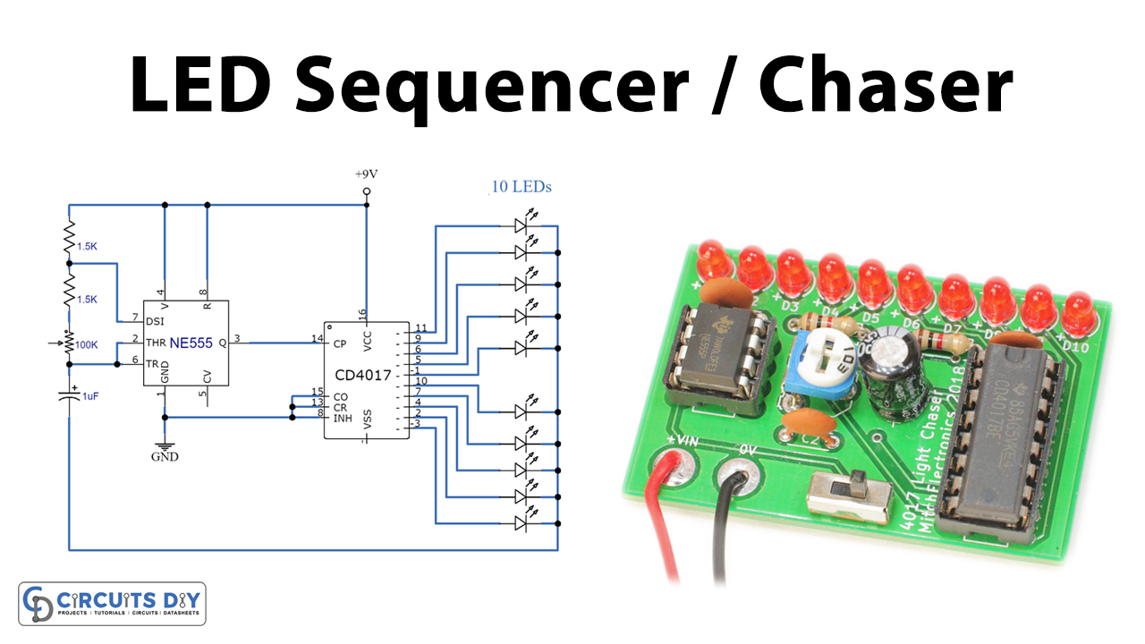
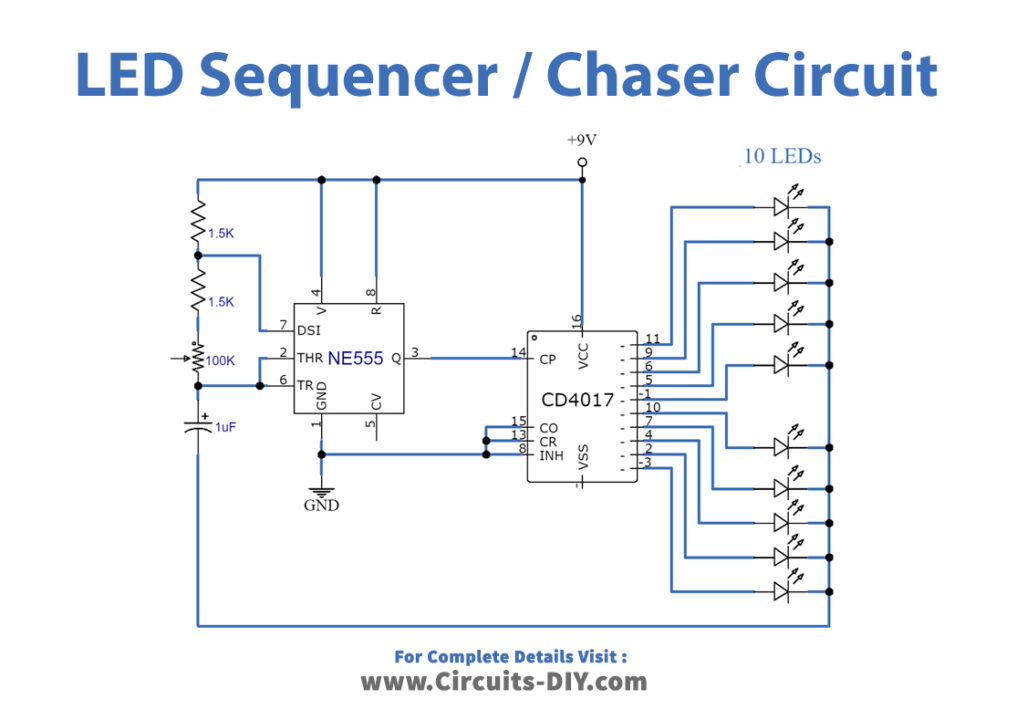
In this tutorial, we are going to demonstrate a LED sequencer/ chaser using NE555 & CD4017. The purpose of this circuit is to turn the LEDs on one by one.
CD4017 is a CMOS counter IC, it gives 10 outputs according to the clock pulse it receives from the clock input (Pin 14). NE 555 is a timer IC which is a very versatile IC widely used in various electronic projects for different tasks. In this project, we are using this IC as an Astable multivibrator whose output produces a continuous trigger pulse for the CD4017 counter. This results in the chasing light effect of the circuit.
Hardware Components
The following components are required to make LED Chaser Circuit
| S.no | Component | Value | Qty |
|---|---|---|---|
| 1. | Battery | 9V | 1 |
| 2. | Resistors | 1.5K | 2 |
| 3. | Variable Resistor | 100K | 1 |
| 4. | Electrolytic Capacitor | 1µF | 1 |
| 5. | IC | NE555 Timer | 1,1 |
| 6. | Decade Counter Divider IC | CD4017 | |
| 7. | LEDs | – | 10 |
CD4017 Pinout
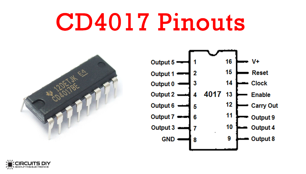
For a detailed description of pinout, dimension features, and specifications download the datasheet of CD4017
NE555 IC Pinout

For a detailed description of pinout, dimension features, and specifications download the datasheet of 555 Timer
LED Chaser Circuit
Circuit Explanation
The 555 timer IC is wired as an astable multivibrator and its output is connected to the clock input of CD 4017 IC. The output frequency of the 555 timers is dependent on the resistors, variable resistors,s, and capacitors. VCC (pin 8) and GND (pin 1) is connected to the power supply. Reset (pin 4) is connected directly to the positive power supply to avoid an accidental reset of the 555 timers.
Now in CD4017 VDD (pin 16) and VSS (pin 8) is connected to the power supply directly. Clock enable (pin 13) is an active low input, so it is connected to the ground. The clock input (pin 14) is connected to the output pin of the 555 timers. All the decoded output pins are connected with LEDs.
Working Explanation
This circuit is operating at 9 volts. When the power is applied, LEDs start to glow one by one for a defined period. 555 timer IC generates a frequency signal which is adjusted by the variable resistor of 100K when we change its value the speed of the LEDs is changed as well because the frequency of the 555 timer increases and this increases the frequency signal given at trigger input pin of Counter IC. So the counter changes its state faster. This cycle of blinking of LEDs keeps repeating itself until the power of the circuit is turned OFF.