
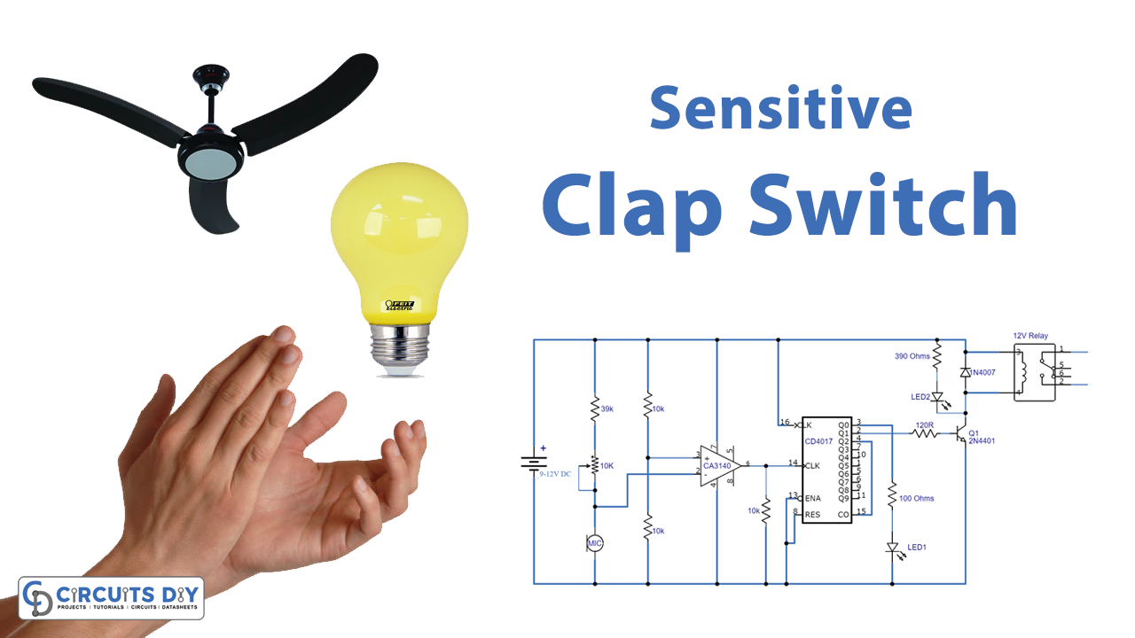
In this tutorial, we are going to show you how to make a Sensitive Clap Switch. The clap switch turns the light on with the sound of a clap. Even though its name is clap switch but it’s not restricted to just the sound of a clap. It turns the light on with any sound that has the approximately same pitch as the sound of a clap.
For those who are learning about projects related to electronics, the Sensitive clap switch is a good project for them. It’s easy to make and keeps the process interesting as well. This circuit is effective and quite sensitive to sound because we are using an electret mic as a sensor.
Hardware Components
The following components are required to make Clap Switch Circuit
| S.no | Component | Value | Qty |
|---|---|---|---|
| 1. | IC | CA3140 | 1 |
| 2. | SPDT Relay | 9V/12V | 1 |
| 3. | Decade Counter IC | CD4017 | 1 |
| 4. | Transistor | 2N4401 | 1 |
| 5. | LEDs | – | 1 |
| 6. | Resistor | 39K, 10K, 390ohms, 120R, 100ohms, | 1,3,1,1,1 |
| 7. | Electret Mic | – | 1 |
| 8. | Diode | 1N4007 | 1 |
| 9. | DC Supply | 9-12V | 1 |
| 10. | Breadboard | – | 1 |
CD4017 Pinout

For a detailed description of pinout, dimension features, and specifications download the datasheet of CD4017
CA3140 Pinout

For a detailed description of pinout, dimension features, and specifications download the datasheet of CA3140
Clap Switch Circuit

Working Explanation
The operating voltage of this circuit is 9-12V. IC1 is an operational amplifier that is merged with IC2 that acts in toggle mode. Then connected to a transistor which acts as the driving force of the relay. Relay is joined to a bulb or any electronic device. Now let’s take a look at how this circuit actually works,
Resistors and a variable resistor adjust the sensitivity of the operational amplifier and mic. Mic senses the sound from 5-10 meters away. It can hear a clap, whisper, or a finger snap and gives the output to the input of the op-amp, the output pulses are amplified and passed to the input of IC2. We have to use another resister of 10K at the input of IC2 to prevent false triggering.
IC2 acts as a toggle switch, it gives output through pins 2 and 3 when the input pin14 receives a pulse. Pin4 is connected to pin15 so that further counting would be hampered. When the output is HIGH it passes to the base of the Transistor through a resistor when it starts working relay will energize and a light bulb or any electrical appliances that are joint to the relay will be activated. If the output pin becomes LOW the relay will switch off and LED2 will turn on which indicates the OFF position of the switch.
Applications and Uses
This circuit can be used in,
- Tubelights
- Bulb
- Radio
- Fan


Can this circuit be simulated in any software?
Yes you can simulate this best on PROTEUS