Timers are an essential part of many electronic circuits or appliances. You can find them in the devices around you such as microwave ovens or washing machines. This kind of device uses timers to switch the loads for a particular period of time. In the early days, the operator had to manually control these loads. They had to turn on the load and when the desired conditions were met turn the load off by themselves. But with this circuit, these things can be done automatically.
This circuit is a multi-stage adjustable long-duration timer. It is based on two ICs. One is a 555 timer IC, which provides 2-3 timer circuits in one integrated circuit. It is cheap and convenient to use. The other IC is a decade counter IC CD 4017.

Hardware Components
The following components are required to make Long Duration Timer Circuit
| S.no | Component | Value | Qty |
|---|---|---|---|
| 1. | DC Supply | 5-12V | 1 |
| 2. | Breadboard | – | 1 |
| 3. | IC | NE555 Timer | 1 |
| 4. | Decade Counter IC | CD4017 | 1 |
| 5. | Diode | 1N4148 | 2 |
| 6. | Transistor | 2N3904 | 1 |
| 7. | Resistors | 1K, 220Ω | 2,1 |
| 8. | Electrolytic Capacitor | 1000µF | 1 |
| 9. | Ceramic Capacitor | 0.01µF | 1 |
| 10. | Relay | – | 1,1 |
| 11. | Diode | 1N4007 | 1 |
| 12. | Variable Resistor | 5M | 1 |
NE555 IC Pinout

For a detailed description of pinout, dimension features, and specifications download the datasheet of 555 Timer
CD4017 Pinout
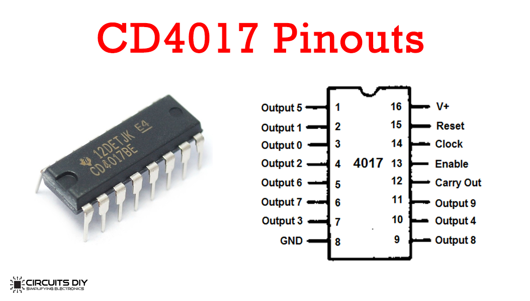
For a detailed description of pinout, dimension features, and specifications download the datasheet of CD4017
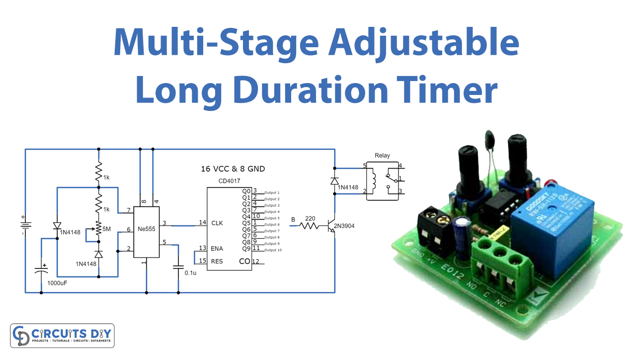
Long Duration Timer Circuit
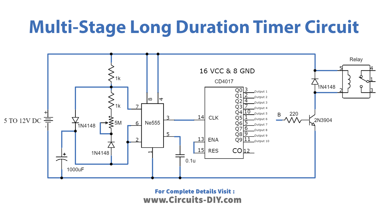
Working Explanation
The operating voltage of this circuit is 5V to 12V DC. This circuit is versatile and completely adjustable according to your needs. It provides different timing cycles. IC1 is working as an oscillator generating clock pulses, which can be adjusted through a 5M variable resistor. There are 10 output stages in this circuit which are marked in the circuit diagram as outputs 1 to 10. IC2 is responsible for providing 10 timings outputs.
These outputs are adjustable through the variable resistor, if you adjust the circuit to activate each output after 1 hour then output 4 will be activated after 4 hours and output 10 after 10 hours. The gap between each output can also be increased by increasing the value of the 1000uF resistor. Increasing its value to 2200uF or 4700uF will increase the gap to 2-4 hours.
You can also select the desired hour on which you want to activate the relay by connecting point B with it. Always remember to use a relay having the same voltage as the input voltage of your circuit.
Applications and Uses
- Microwave ovens
- Alarms
- Washing machines
- Circuits