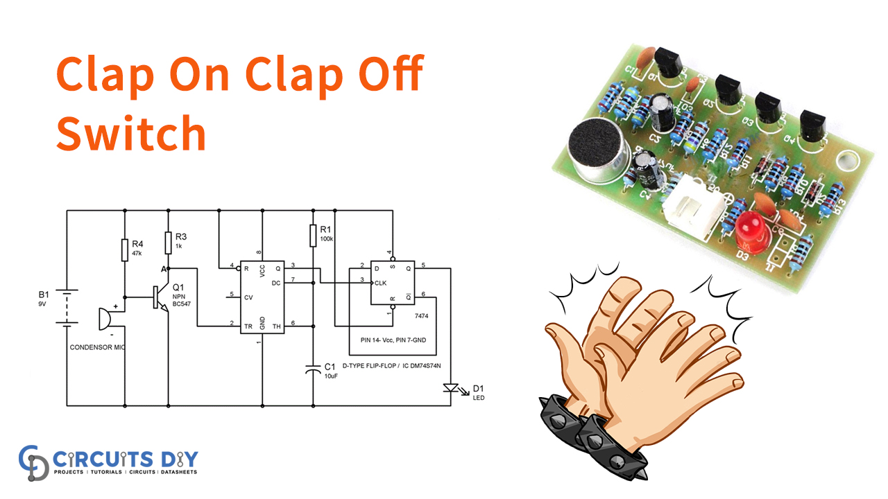
Here is an astounding project that might use in several automation system projects, a “Clap On Clap Off” switch. A “Clap On Clap Off” switch is a fascinating idea that could utilize in home automation. It functions as a switch that makes gadgets On and Off by making a clap sound. So this is the Clap Switch which will turn ON with the first Clap and turn Off with the subsequent second Clap.
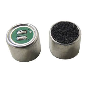
In spite of the fact that its name is “Clap switch”, yet it tends to turn ON by any stable of about the same pitch as the Clap sound. Meanwhile, the fundamental segment of the circuit is the Electric Condenser Mic, which utilizes as a sound sensor. Condenser Mic fundamentally changes over sound energy into electrical energy. However, that goes used to trigger 555 clock IC, through a Transistor.
Moreover, triggering off of 555 IC is used here as a Clock pulse generator for D-type flip-flop. Henceforth, it would turn ON the LED, which will stay ON until the following clock pulse implies the following Clap sound.
In the event that we eliminate the D-type Flip-flop from the circuit, the LED will automatically turn OFF after some time. However, this time will be 1.1xR1xC1 seconds depending on the resistance and capacitor value.
Hardware Components
The following components are required to make Clap Switch Circuit
| S.no | Component | Value | Qty |
|---|---|---|---|
| 1. | Condenser Mic | – | 1 |
| 2. | Transistor | BC547 | 1 |
| 3. | IC | NE555 Timer | 1 |
| 4. | Variable Resistor | 1 K47 K100 K | 1 |
| 5. | Capacitor | 10uF | 1 |
| 6. | IC | 7474 | 1 |
| 7. | LED | – | 1 |
| 8. | Battery | 9 V | 1 |
NE555 IC Pinout

For a detailed description of pinout, dimension features, and specifications download the datasheet of 555 Timer
Clap Switch Circuit
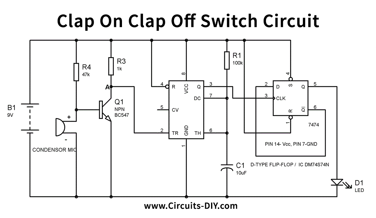
Working Explanation
The circuit operates in such a way that when we produce some solid clap sound close to the condenser mic, this sound will be changed over into electrical energy. Hence, it will raise the potential at the Base, which will turn the Transistor ON. When the transistor turns ON, the potential at Point A would turn out to be Low and it will trigger the 555 IC due to the low voltage (beneath Vcc/3) at Trigger Pin 2. So the yield PIN3 will be high and a positive clock pulse will apply to D-type Flip-flop. Moreover, it makes Flip-flop actuate and the LED will turn ON. This SET condition of the flip-flop will stay until the following clock pulse (next Clap).
Here we are utilizing 555 clock IC in Monostable Mode, whose yield (PIN 3 of 555 IC) utilizes here as a clock pulse generator for D-type Flip-flop. So the clock pulse will be HIGH for 1.1xR1xC1 seconds and afterward, it would turn out to be LOW.
Applications and Uses
Common applications are:
- Automatic Home lighting, radio, television, fans, and other electrical appliances i.e. to turn them ON and OFF.