Generally, a tracking transmitter communicates a radio signal which can be distinguished by a directional antenna (regularly a Radio Direction Finder). Although by pivoting the reception apparatus or antenna, one can decide the signal direction, the message lies in, and obviously whatever it might connect to. Meanwhile, the EPIRB is a case of a similar tracking transmitter device.
Moreover, the circuit design here is a simple tracking transmitter that utilizes 555 timer IC, a 2N2222 transistor, a set of resistors, capacitors, and a few other components.
Hardware Components
| S.no | Component | Value | Qty |
|---|---|---|---|
| 1. | IC | NE555 Timer | 1 |
| 2. | Transistor | 2N2222 | 1 |
| 3. | Antenna | – | 1 |
| 4. | Inductor | 2 turns | 1 |
| 5. | Variable Capacitor | – | 1 |
| 6. | Capacitor | 10nF, 100nF, 1nF, 28pF, 5pF, 62pF, 2pF | 3, 1, 1, 1, 1, 1, 1 |
| 7. | Resistor | 18kΩ , 100Ω, 39kΩ, 82kΩ | 1, 1, 1, 1 |
| 8. | Battery | 4.5 Volts | 1 |
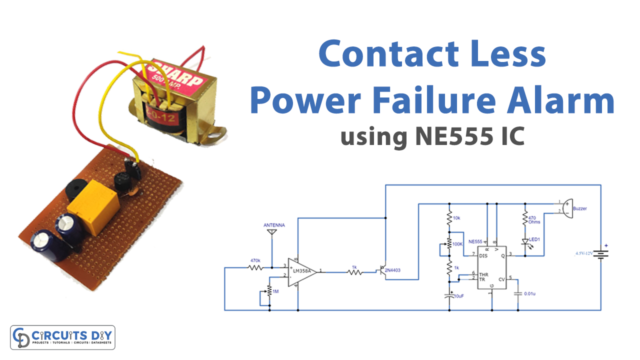
Circuit Diagram
Circuit Operation
Accordingly, the schematic that appeared here is a circuit of a 555-tracking transmitter. However, the 555 is a well-known adaptable IC utilized in numerous electronic devices. In the above-mention reference circuit, this IC is likewise used to create a tone that communicates through the FM transmitter circuit. Meanwhile, it works around the 2N2222 semiconductor.
However, the circuit tune is between 103 to 108 MHz and will convey a good way off of 100m. Therefore, L1 is equivalent to 2 turns of #24 wire on a 5mm structure, and TR is equivalent to 1 to 30 pf trimmer capacitor. A radio wire can be a 75cm wire, for full range keep the wire vertical, or you can likewise utilize a little 6-or 12-inch cable as a reception apparatus or antenna, yet the field will turn out to be half or less. Moreover, the circuit work with 4.5-volt batteries of any sort.
Applications and Uses
It is commonly used in the following applications:
- Model rocketry
- Remote-control aircraft