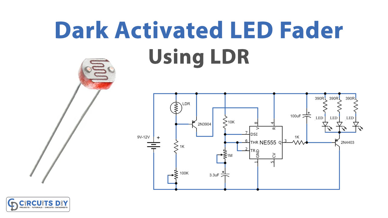
Here is an intriguing DIY project of a dark-activated LED Fader circuit that is going to be discussed here in detail. Therefore, when the light does not reach the surface of the LDR, the circuit can fade in and out of three LEDs automatically. However, the affectability of the dark sensor balances with the 100K variable resistor. And fading of the LEDs is adjusted with the 1M variable resistor.
The LED stands for light-emitting diode; it is a semiconductor source of light when the current passes through it will discharge light. The Fader circuit uses here with LED light to give brightening and fading effects. Usually, there are various implementations like Automobile DRLs (Daytime Running lights), decorating houses, regular lamps, energy lights,s, etc. Meanwhile, the intensity of fading depends upon entering or leaving a particular place or room.

Hardware Components
The following components are required to make a dark-activated LED Fader Circuit
| S.no | Components | Value | Qty |
|---|---|---|---|
| 1. | IC | NE555 Timer | 1 |
| 2. | LDR | – | 1 |
| 3. | Transistor | 2N3904, 2N4403 | 1 |
| 4. | Battery | 9V – 12V | 1 |
| 5. | LED | – | 3 |
| 6. | Resistor | 390R, 1K, 10K | 3, 2, 1 |
| 7. | Electrolytic Capacitor | 3.3uF, 100uF | 1 |
| 8. | Variable resistor | 1M, 100K | 1 |
NE555 IC Pinout

For a detailed description of pinout, dimension features, and specifications download the datasheet of 555 Timer
Dark Activated LED Fader Circuit
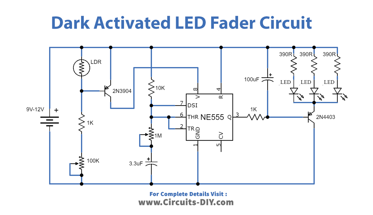
Working Explanation
The working of the circuit is straightforward the circuit divides into two phases. The primary stage is a dark sensor circuit. The first stage works around a 2N3904 semiconductor. However, the second stage is an LED fader circuit that wires around a 555-clock IC. At the point when the light is missing on the surface of the LDR, its obstruction rises. Because of this the semiconductor will get impelled and actuate the LED fader circuit.
The number of LEDs can likewise be expanded with their current constraining resistor which is 390R. A higher yield PNP semiconductor in the spot of 2N4403 can also be utilized; therefore, if you need to use a light or need a few more LEDs. For instance, you can use a BD140 or other higher-yield power semiconductor that will likewise work here. The working voltage of the circuit is 9V to 12V DC. However, it can likewise be worked with lower voltages beginning from 4.5V DC. To operate the circuit with lower voltages, make a point to utilize the reasonable current constraining resistor with LEDs, or the LEDs won’t light more splendidly.
The circuit can be used efficiently for generating spooky effects in idols. The circuit requires just a couple of op-amps and some other passive components for applying the proposed brightening and fading action in LEDs. Here the ICs are used with a dual lamp. The op-amp is used for generating a gradual rising and sinking voltage. The op-amp is configured as a comparator for supplying an alternatively varying voltage to charge or discharge a constant current input.
Applications and Uses
The circuit can be used in Shopping malls to fade out the light in places where there is no crowd. Fading LEDs can be used in security applications to alert something. These can be used in home applications and can be used in cars as indicators with some charges