Introduction
LDR, a Light-dependent resistor, as the name implies resists light. Hence, resistance increases as the light intensity got increases. At dark, the circuit works. We can make many circuits using LDR. But, in this tutorial, we are going to “LDR Switch Relay Circuit”. It means the relay switch gets turned ON when there is no light. Hence you can add any other device to that relay switch. For example, you can connect the light to the output relay and can make a street light circuit. You can also make lamp circuits through that. You can ON DC motors using the same circuit. Remember, that this circuit uses CD4017 IC. So let us first see its pin configuration.

Pin Configuration of IC CD4017
- Output Pins: from pin 1 to pin 7 and pin 9 to pin 11.
- Input Voltage pin: Pin 16 is for the applied voltage from 3V to 15V,
- Ground pin: pin 8 is for ground.
- Clock Enable Pin: Pin 13 is for the clock, when there’s logic zero, the clock gets enabled and the counter increases one count for every clock pulse. When there’s logic one, the clock input gets stopped, and the counter does nothing when the pulse arrives.
- Clock Pin: Pin 14 is the clock pin. The clock pulse must not be noisy, otherwise counter may get increased more than once
- Reset Pin: Pin 15 is a reset pin, normally it is at logic zero, when it gets one, the counter resets to zero. This pin can reset the counter and restart the counting from 0. Thus, for the normal process of a circuit, this has to be kept LOW.
Hardware Required
| S.no | Component | Value | Qty |
|---|---|---|---|
| 1. | LDR (Light Dependent Resistor) | – | 1 |
| 2. | IC | CD4017 | 1 |
| 3. | IC | LM358 | 1 |
| 4. | Relay module | 9V | 1 |
| 5. | Transistor | BC547 | 1 |
| 6. | Potentiometer | 10KΩ | 1 |
| 7. | Diode | 1N4007 | 1 |
| 8. | LED | – | 1 |
| 9. | Capacitor | 33uF / 16V | 1 |
| 10. | Resistor | 10KΩ, 100KΩ, 330Ω | 2, 1, 1 |
| 11. | AC Supply | 230V | – |
| 12. | Battery | 9V | 1 |
| 13. | 2-Pin Connector | – | 2 |
Circuit Diagram
Working Explanation
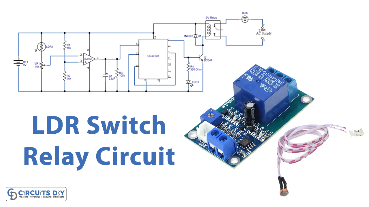
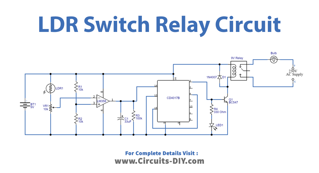
In this LDR switch relay circuit, there are two parts. At first, there is an LDR sensor and an operational amplifier. While the second part includes the decade counter which is driving the Relay. We connected LDR with potentiometer VR1 and we connected the variable terminal with the inverting input of the operational amplifier. Now by changing the value of this variable resistor, you can adjust the sensitivity level of LDR. We balance the non-inverting input of the operational amplifier with a Voltage divider which we have made using resistors R1 and R2. PIn of the operational amplifier gives the output and which we give to a clock input of Decade counter IC. Now, This IC counts the clock and produces ten outputs from Q0 to Q9. At Q0 we have connected the output relay with the help of switching transistor BC547 and an LED1 shows the ON condition of the relay. You can connect any electrical appliance like the bulb, fan, motor, etc between a normally open pin, and a Common pin. When the LDR detects the dark or shadow, the relay makes the connection to the supply and turns ON the electrical appliance which remains ON in the same condition until an LDR detects another shadow.
Application and Uses
- In street lights.
- Home automation systems.
- To operate any electrical appliance in dark, etc.