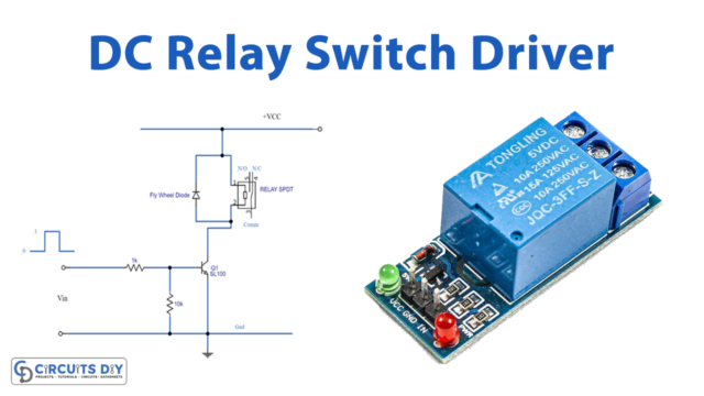
To begin with the introduction of the “Motor Controller Circuit”, a motor controller is an electrical or electronic device that utilizes to control the speed of a motor attached to any microcontroller, battery, or engine.
However, a motor controller is a crucial component because a microcontroller can typically provide generally 0.1 Ampere of current whereas most actuators require several Amperes. In short, motor controllers are such devices that manage the smooth operation of an electric motor.
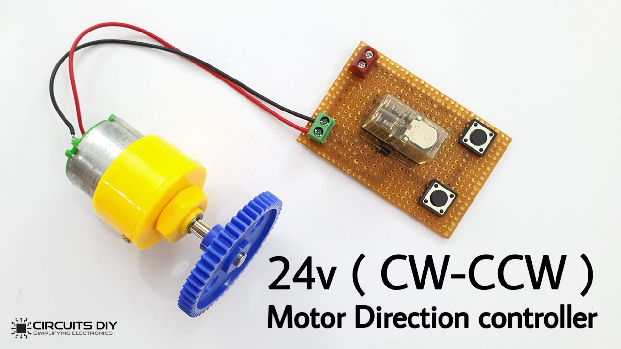
Furthermore, in this circuit, we are going to provide a short instructional tutorial that is easy to fabricate and economical to purchase. This circuit drives a 24V DC motor with the help of a 24V DPDT relay. Now, it’s up to you to choose the value of the relay according to the value of the voltage rating of your motor, whereas all the other procedures would be the same.
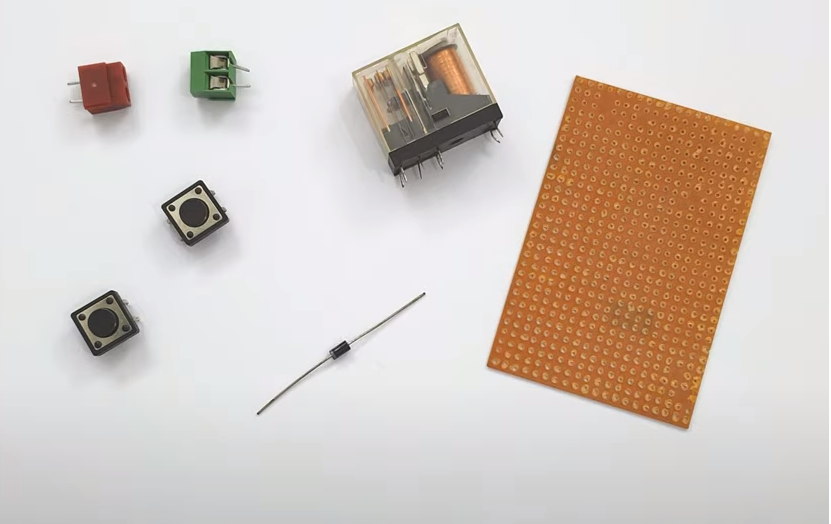

Hardware Components
The following components are required to make Motor Controller Circuit
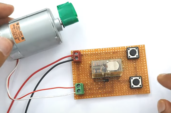
[inaritcle_1]Motor Controller Circuit
Useful Steps
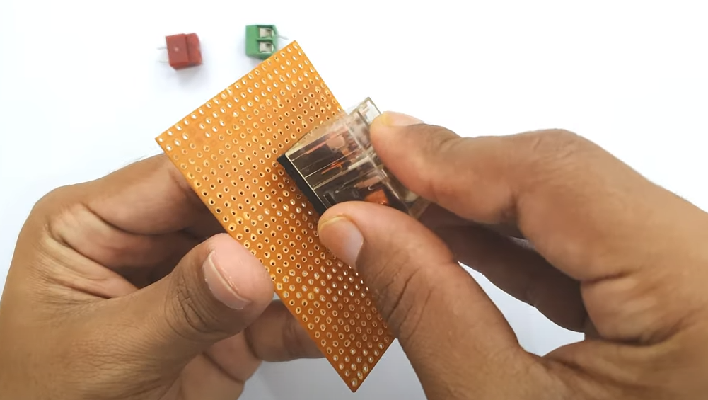
Step# 01
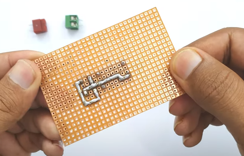
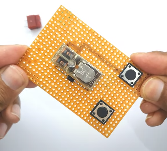
Install Relay into PCB board, and connect relay’s NO (normally open) pin of side 1 to the NC (normally closed) pin of side 2. While NC pin of side 1 to NO pin of side 2.
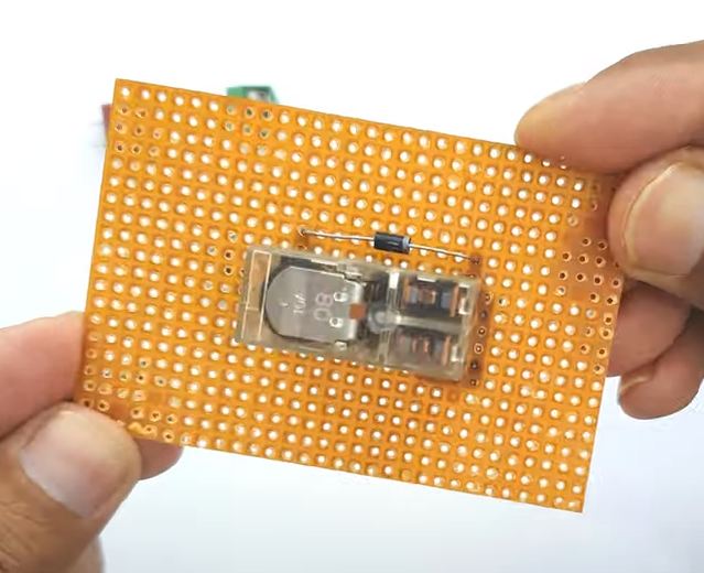
Step# 02
Solder the IN4007 diode in a fashion where the cathode of the IN4007 diode is connected to the relay pin and the anode of 1N4007 is connected to the NO pin of side 2.
Step# 03
For clockwise rotation (CW), connect the Vcc of switch S1 to the anode of 1N4007 diode.
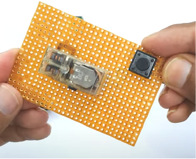
Step# 04
For counterclockwise rotation (CCW), connect the Vcc of switch S2 to the cathode of the 1N4007 diode.
Step# 05
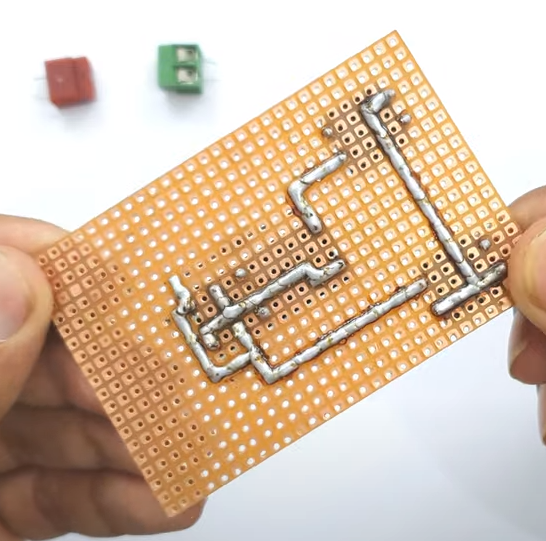
Connect the terminal block 1 for power supply input. Positive on Vcc and negative on relay side 1 NO pin.
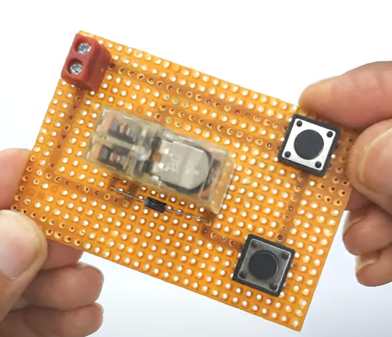
Step# 06
Connect terminal block 2 for relay connection. From the common pin of the relay
Step# 07
Now connect terminal block 1 with 24V input and terminal block 2 with the motor.
Circuit Operation
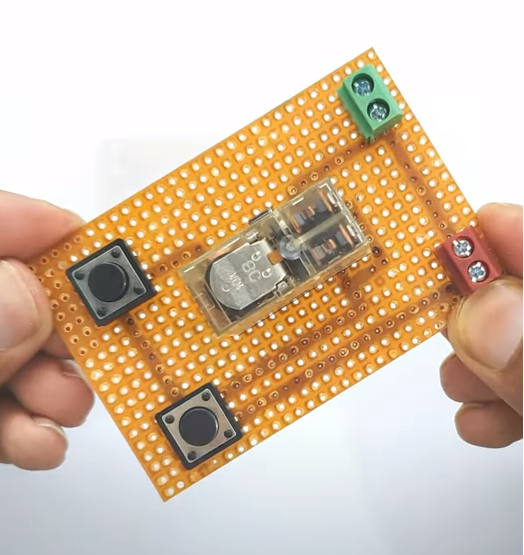
The circuit operates in such a way that the 24V DPDT relay regulates the power input from the power source to the motor. The motor controller circuit additionally connects with two electronic switches and two terminal blocks. When the switch S1 is pressed the circuit allows the motor to rotate in the clockwise direction. However, when the switch S2 is pressed the circuit allows the motor to rotate in the counter-clockwise direction.
Applications and Uses
- The primary use of this motor controller is to rotate a 24V DC motor in both CW and CCW directions.
- It can also use in microcontroller circuits.