Introduction
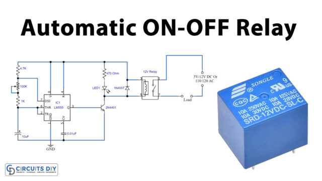
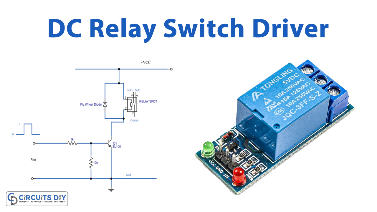
In this tutorial, we are going to study the “DC Relay Switch Driver Circuit”. A basic electromechanical switch is referred to as a relay. While regular switches are used to manually close or open circuits, a relay is a switch that connects or disconnects two circuits. A DC relay switch uses a DC (Direct Current) source to energize an electromagnetic coil in a relay.
The electromagnetic induction principle governs the operation of a relay. When we apply a current to an electromagnet, it creates a magnet around it. The copper coil and iron core operate as electromagnets in the relay. When DC is introduced to the coil, it begins to attract the contact as indicated. We call this relay energizing. When you remove the supply, it returns to its original position. This is referred to as relay de-energization.
Hardware Components
The following components are required to make the Relay Switch Driver Circuit
| S.no | Component | Value | Qty |
|---|---|---|---|
| 1. | Relay SPDT | – | 1 |
| 2. | Diode | 1N4007 | 1 |
| 3. | Transistor | SL100 | 4 |
| 4. | Resistor | 1KΩ, 10KΩ | 1,1 |
| 5. | Battery | 12V | 1 |
| 6. | 2-Pin Connector | – | 1 |
SL100 Pinout
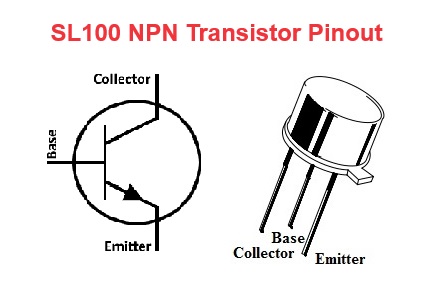
For a detailed description of pinout, dimension features, and specifications download the datasheet of SL100
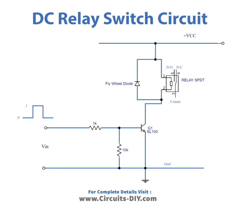
Relay Switch Driver Circuit
Working Explanation
Here we are providing a common application circuit for a DC Relay switch. Through a switching transistor, the magnetic coil is wired to the bias. To shield the coil from back emf, we use a reverse bias flywheel diode across the coil. The coil is immediately connected to bias via the input Vin to the transistor base, which causes conduction through the transistor. It energizes the coil when Vin lowers the transistor to cut and disconnects the relay coil from the bias.
Application and Uses
Relays have a wide range of applications, which include:
- Different DIY projects.
- Industrial applications
- Home automation systems.