In this tutorial, we are demonstrating a project on an RF remote control relay switch circuit. The circuit is utilizing a DPDT relay at the output from which you can interface your home appliances to work remotely like a fan, light, and so forth. The circuit is a receiver and the transmitter can be any FM transmitter. You can likewise utilize any transmitter published on our FM transmitter circuits page with this RF switch circuit.
We have tried the circuit with our best FM transmitter project and it was changing the relay from a separation of 8 to 10 meters or more and across the wall.
Hardware Components
The following components are required to make the Remote Control Relay Switch circuit
| S.no | Components | Value | Qty |
|---|---|---|---|
| 1 | IC | CD4017 | 1 |
| 2 | IC | CA3140 | 1 |
| 3 | Transistor | 2N4401, 2N4403 | 2, 1 |
| 5 | Diode | 1N34 | 1 |
| 6 | Diode | 1N4007 | 1 |
| 7 | Relay | 12V | 1 |
| 8 | LED | – | 2 |
| 9 | Antenna | 90cm | 1 |
| 10 | Variable Capacitor | 1 – 35pF | 1 |
| 11 | Resistor | 1K, 10K, 1M, 390Ω, 120R | 3, 1, 1, 1, 1 |
| 12 | Battery | 9 – 12V | 1 |
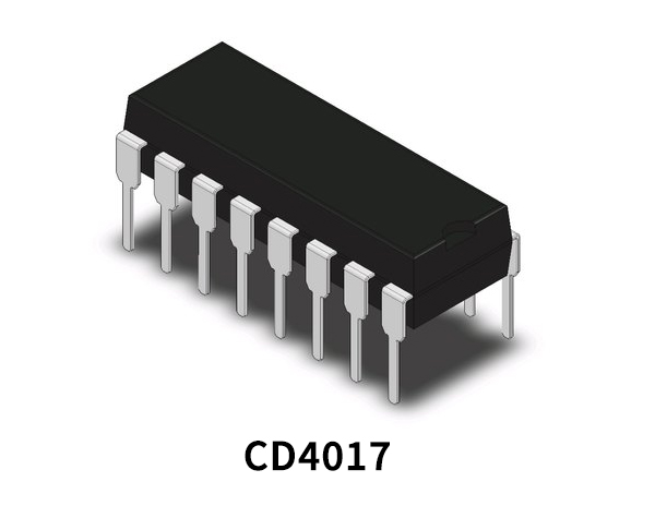
CD4017 Pinout
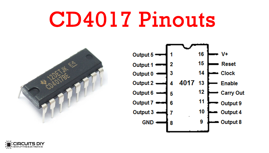
For a detailed description of pinout, dimension features, and specifications download the datasheet of CD4017
CA3140 Pinout
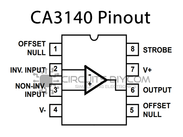
For a detailed description of pinout, dimension features, and specifications download the datasheet of CA3140
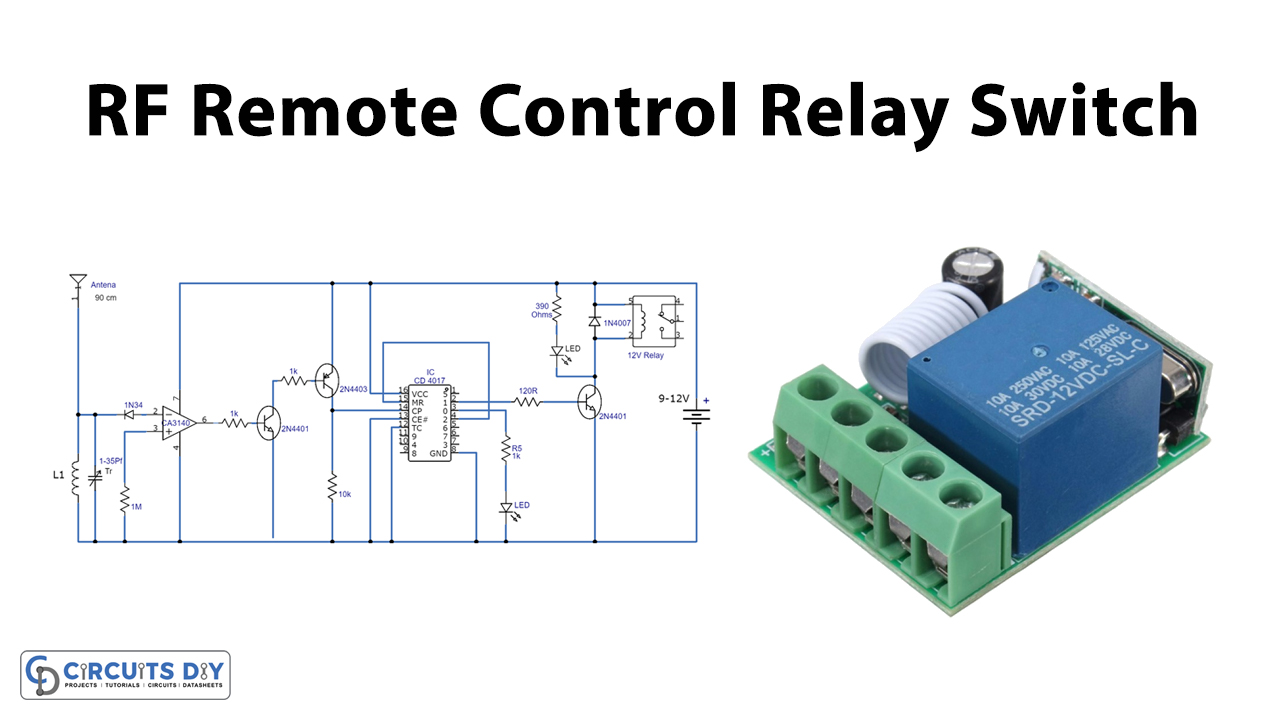
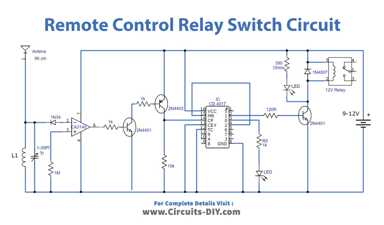
Remote Control Relay Switch Circuit
Working Explanation
In this section, we are discussing the operation of the circuit. Operating the transmitter with a 9-volt battery will expand the range more, or for additional expanding the range you can likewise utilize a powerful FM transmitter like a long-range stable FM transmitter or other high-power FM transmitter circuit diagrams you have. A microphone with the transmitter is not required because the circuit just detects the RF field generated from the transmitter.
After finishing both the parts of the task for example transmitter and receiver, first, tune the FM transmitter from 1 or 2 meters to the separation until the relay becomes switched on. After that make more separation between the transmitter and beneficiary and alter the trimmers at the two sides.
L1 is an air-cored coil, having 6 turns of #24 enameled wire coiled on a 5mm structure. Use a 90cm telescope antenna on the two sections for example transmitter and receiver.
Applications and Uses
Remote Control Relay Switch has wide applications which are the following:
- It is used to control home appliances like lights, fans, doorbells, etc.
- It can also be used in industrial and security use like wireless security alarms, remote controllers, motors, etc.