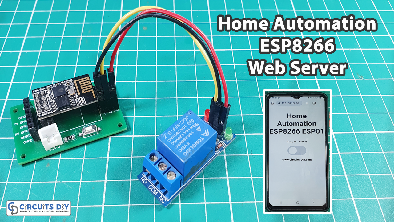
Hey techies, have you ever imagined that you can control your home appliances remotely? In this tutorial, we are going to make “Home Automation using ESP8266 ESP01 Web Server & Relay Module” to control Home appliances from the Local Networks. Using relays with the ESP8266 ESP01 is the best way to remotely control any AC home appliances.
Basically, We will build a web server to see how the relay module works, how to connect the relay to the ESP8266, and control a relay (or as many relays as you want) remotely. So let’s get Started!
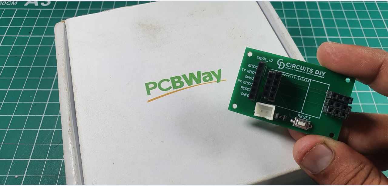
PCBWay commits to meeting the needs of its customers from different industries in terms of quality, delivery, cost-effectiveness, and any other demanding requests. As one of the most experienced PCB manufacturers in China. They pride themselves to be your best business partners as well as good friends in every aspect of your PCB needs.
Hardware Components
The following components are required to make Home Automation Circuit
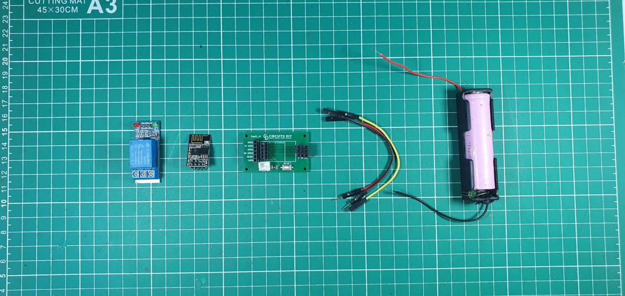
| S.No | Components | Value | Qty |
|---|---|---|---|
| 1 | ESP01 | 1 | |
| 2 | DC Relay Module | 5V | 1 |
| 3 | SMD Resistor | 10K | 1 |
| 4 | SMD Button | 1 | |
| 5 | Lithium Cell | 3.7v | 1 |
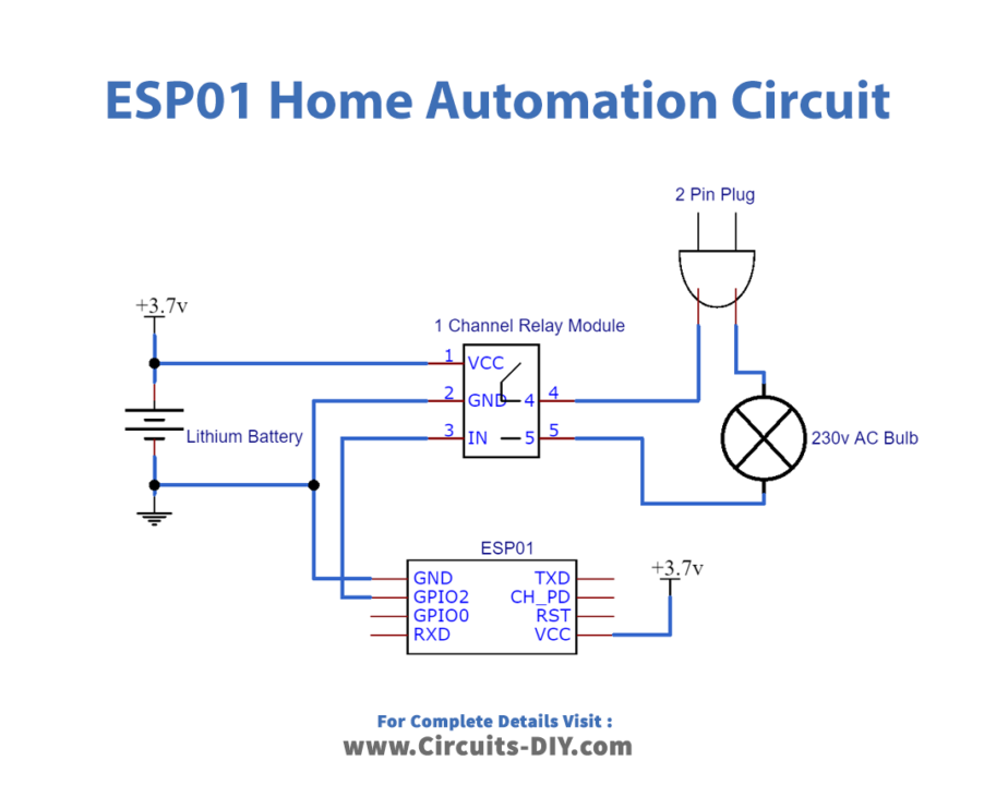
Home Automation Circuit
ESP8266 ESP01 Home Automation Code
// Import required libraries
#include "ESP8266WiFi.h"
#include "ESPAsyncWebServer.h"

// Set to true to define Relay as Normally Open (NO)
#define RELAY_NO    true

// Set number of relays
#define NUM_RELAYS  1

// Assign each GPIO to a relay
int relayGPIOs[NUM_RELAYS] = {2};

// Replace with your network credentials
const char* ssid = "Circuits DIY";
const char* password = "03433212601";

const char* PARAM_INPUT_1 = "relay";
const char* PARAM_INPUT_2 = "state";

// Create AsyncWebServer object on port 80
AsyncWebServer server(80);

const char index_html[] PROGMEM = R"rawliteral(
<!DOCTYPE HTML><html>
<head>
  <meta name="viewport" content="width=device-width, initial-scale=1">
  <style>
    html {font-family: Arial; display: inline-block; text-align: center;}
    h2 {font-size: 3.0rem;}
    p {font-size: 3.0rem;}
    body {max-width: 600px; margin:0px auto; padding-bottom: 25px;}
    .switch {position: relative; display: inline-block; width: 120px; height: 68px}
    .switch input {display: none}
    .slider {position: absolute; top: 0; left: 0; right: 0; bottom: 0; background-color: #ccc; border-radius: 34px}
    .slider:before {position: absolute; content: ""; height: 52px; width: 52px; left: 8px; bottom: 8px; background-color: #fff; -webkit-transition: .4s; transition: .4s; border-radius: 68px}
    input:checked+.slider {background-color: #2196F3}
    input:checked+.slider:before {-webkit-transform: translateX(52px); -ms-transform: translateX(52px); transform: translateX(52px)}
  </style>
</head>
<body>
  <h2>Home Automation ESP8266 ESP01</h2>
  %BUTTONPLACEHOLDER%
<script>function toggleCheckbox(element) {
  var xhr = new XMLHttpRequest();
  if(element.checked){ xhr.open("GET", "/update?relay="+element.id+"&state=1", true); }
  else { xhr.open("GET", "/update?relay="+element.id+"&state=0", true); }
  xhr.send();
}
 </script>
 <h3>www.Circuits-DIY.com</h3>
</body>
</html>
)rawliteral";

// Replaces placeholder with button section in your web page
String processor(const String& var){
  //Serial.println(var);
  if(var == "BUTTONPLACEHOLDER"){
    String buttons ="";
    for(int i=1; i<=NUM_RELAYS; i++){
      String relayStateValue = relayState(i);
      buttons+= "<h4>Relay #" + String(i) + " - GPIO " + relayGPIOs[i-1] + "</h4><label class=\"switch\"><input type=\"checkbox\" onchange=\"toggleCheckbox(this)\" id=\"" + String(i) + "\" "+ relayStateValue +"><span class=\"slider\"></span></label>";
    }
    return buttons;
  }
  return String();
}

String relayState(int numRelay){
  if(RELAY_NO){
    if(digitalRead(relayGPIOs[numRelay-1])){
      return "";
    }
    else {
      return "checked";
    }
  }
  else {
    if(digitalRead(relayGPIOs[numRelay-1])){
      return "checked";
    }
    else {
      return "";
    }
  }
  return "";
}

void setup(){
  // Serial port for debugging purposes
  Serial.begin(115200);

  // Set all relays to off when the program starts - if set to Normally Open (NO), the relay is off when you set the relay to HIGH
  for(int i=1; i<=NUM_RELAYS; i++){
    pinMode(relayGPIOs[i-1], OUTPUT);
    if(RELAY_NO){
      digitalWrite(relayGPIOs[i-1], HIGH);
    }
    else{
      digitalWrite(relayGPIOs[i-1], LOW);
    }
  }

  // Connect to Wi-Fi
  WiFi.begin(ssid, password);
  while (WiFi.status() != WL_CONNECTED) {
    delay(1000);
    Serial.println("Connecting to WiFi..");
  }

  // Print ESP8266 Local IP Address
  Serial.println(WiFi.localIP());

  // Route for root / web page
  server.on("/", HTTP_GET, [](AsyncWebServerRequest *request){
    request->send_P(200, "text/html", index_html, processor);
  });

  // Send a GET request to <ESP_IP>/update?relay=<inputMessage>&state=<inputMessage2>
  server.on("/update", HTTP_GET, [] (AsyncWebServerRequest *request) {
    String inputMessage;
    String inputParam;
    String inputMessage2;
    String inputParam2;
    // GET input1 value on <ESP_IP>/update?relay=<inputMessage>
    if (request->hasParam(PARAM_INPUT_1) & request->hasParam(PARAM_INPUT_2)) {
      inputMessage = request->getParam(PARAM_INPUT_1)->value();
      inputParam = PARAM_INPUT_1;
      inputMessage2 = request->getParam(PARAM_INPUT_2)->value();
      inputParam2 = PARAM_INPUT_2;
      if(RELAY_NO){
        Serial.print("NO ");
        digitalWrite(relayGPIOs[inputMessage.toInt()-1], !inputMessage2.toInt());
      }
      else{
        Serial.print("NC ");
        digitalWrite(relayGPIOs[inputMessage.toInt()-1], inputMessage2.toInt());
      }
    }
    else {
      inputMessage = "No message sent";
      inputParam = "none";
    }
    Serial.println(inputMessage + inputMessage2);
    request->send(200, "text/plain", "OK");
  });
  // Start server
  server.begin();
}

void loop() {

}
Working Explanation
First, you need to install NodeMcU in Arduino IDE. Then required necessary libraries to compile this code.
The ESPAsyncWebServer library requires the ESPAsyncTCP library to work. Download both libraries after that in your Arduino IDE, you can go to Sketch > Include Library > Add. ZIP library… and select the library you’ve just downloaded.
After installing the required libraries, copy the following code to your Arduino IDE. We modified this project from Randomnertutorials. You can check the original source for a detailed description.
You can control 4,5,6 different AC or DC appliances using their project. This project is a local area network-based, so you can control it through one device. You have to write your mobile hotspots or network’s SSID and PASSWORD in the code. When the code is uploaded successfully to the NodeMCU then it will generate a local IP address which you can see on the serial monitor screen. When connected to the hotspot it will notify you on the serial monitor screen.