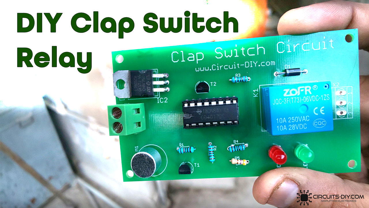
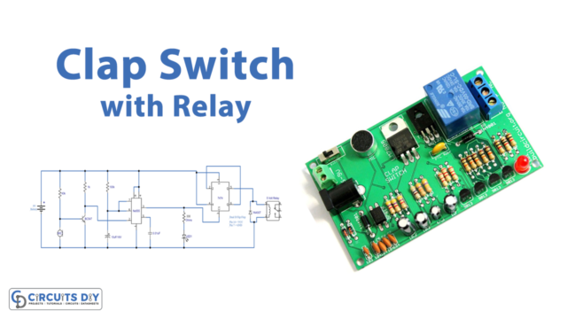
A clap switch circuit is a simple electronic circuit that is used to gain dynamic control of AC/DC appliances by using the application of sound. The sound can either be a simple clapping sound or a knock on an object such as a door. Clap switches have a wide variety of applications, for example, controlling lighting fixtures, AC/DC kitchen appliances, and fail-safe safety equipment. In today’s tutorial, we are going to go over a step-by-step process on how to build a 5v Relay Clap Switch Circuit using the CD4017 decade counter IC.
The heart of this Clap Switch Circuit is a CD4017 IC. A CD4017 IC is a 16-pin CMOS decade counter/Divider IC with 10 outputs. It is also known as the ‘Johnson 10 stage decade counter’. It has 10 decoded outputs that give output signals one by one in sequence when a clock signal from the clock input is given.

PCBWay commits to meeting the needs of its customers from different industries in terms of quality, delivery, cost-effectiveness, and any other demanding requests. As one of the most experienced PCB manufacturers in China. They pride themselves to be your best business partners as well as good friends in every aspect of your PCB needs.
Hardware Components
The following components are required to make Clap Switch Circuit
| S.no | Component | Value | Qty |
|---|---|---|---|
| 1. | Decade Counter IC | CD4017 | 1 |
| 2. | Relay | 5V/SPDT | 1 |
| 3. | Regulator IC | LM7805 | 1 |
| 4. | LED | 5mm, 3.5V | 2 |
| 5. | Transistor | BC547 | 2 |
| 6. | Condensor mic | – | 1 |
| 7. | filament lamp | 220V | 1 |
| 8. | Diode | 1N4007 | 1 |
| 9. | Resistors | 22K, 1K, 470 Ohms | 3 |
| 10. | wall outlet with plug | 220V | 1 |
| 11. | Soldering Iron | 45W – 65W | 1 |
| 12. | Soldering wire with flux | – | 1 |
| 13. | DC Battery | 9v – 12v | 1 |
| 14. | Battery clip | – | 1 |
| 15. | Jumper wires | – | As per need |
CD4017 Pinout
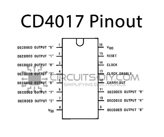
For a detailed description of pinout, dimension features, and specifications download the datasheet of CD4017
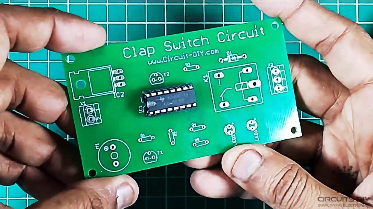
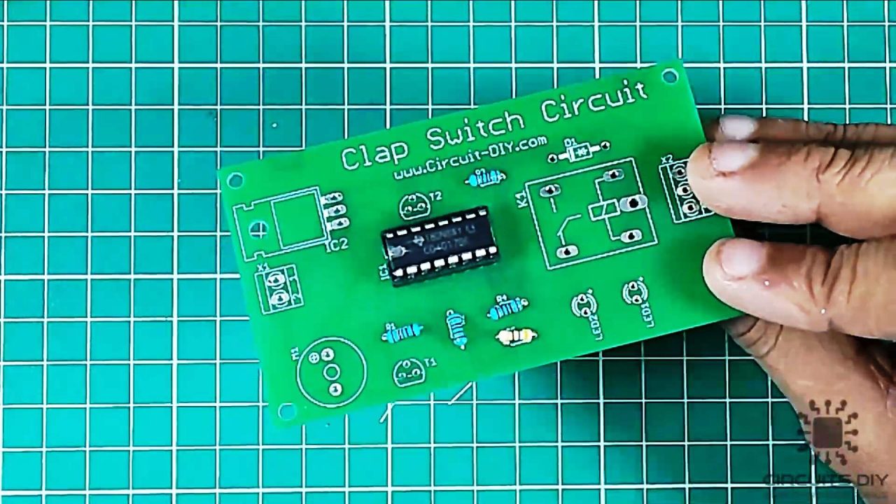
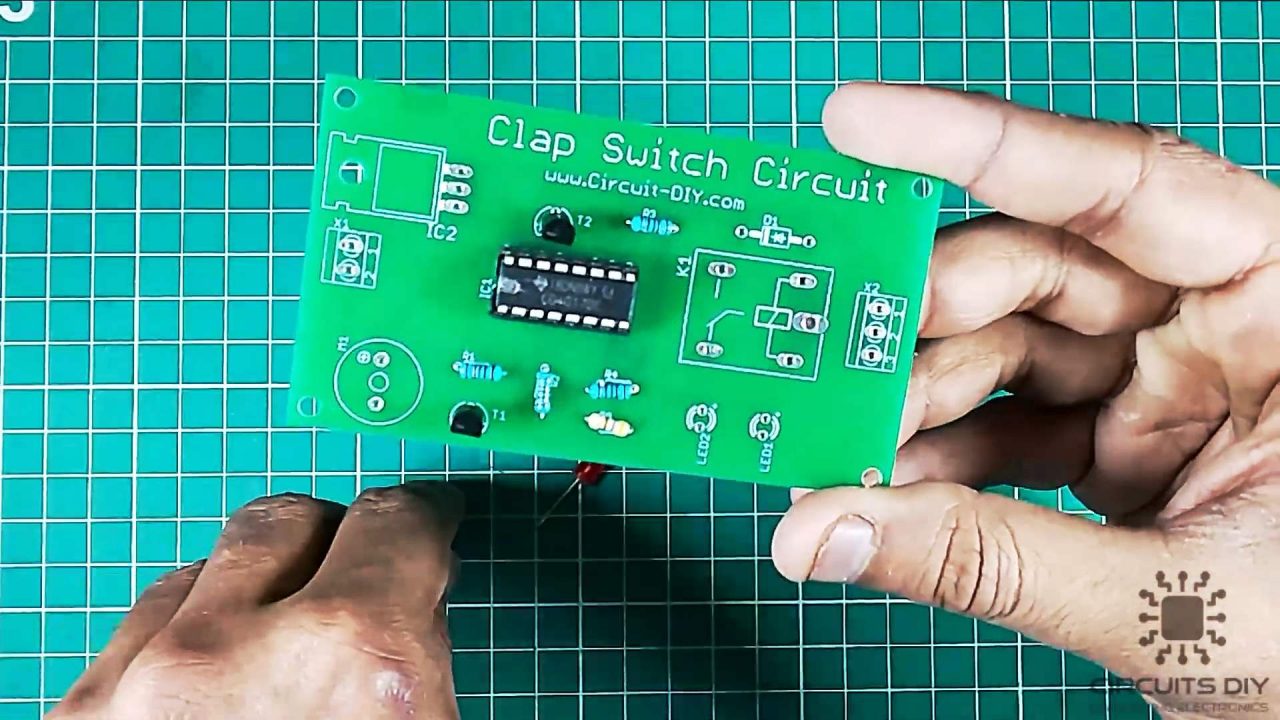
Clap Switch Circuit

Useful Steps
1) Solder the 16 – pin IC base on the PCB board.

2) After that, place the CD4017 in the 16 – pin IC socket.
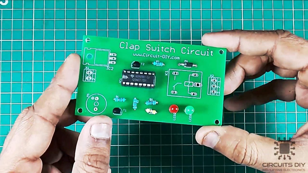
3) Solder all the resistors on the PCB board.
4) After that, solder the BC547 transistors on the PCB board.
5) Solder the 1N4007 flyback diode on the PCB board.

6) After that, solder the two LEDs on the PCB board.
7) Solder the condenser mic and input terminal block connector on the PCB board.
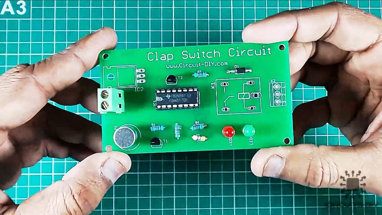
8) Solder the LM7805 voltage regulator on the PCB board.

9) After that, solder the 5V SPDT relay on the PCB board.
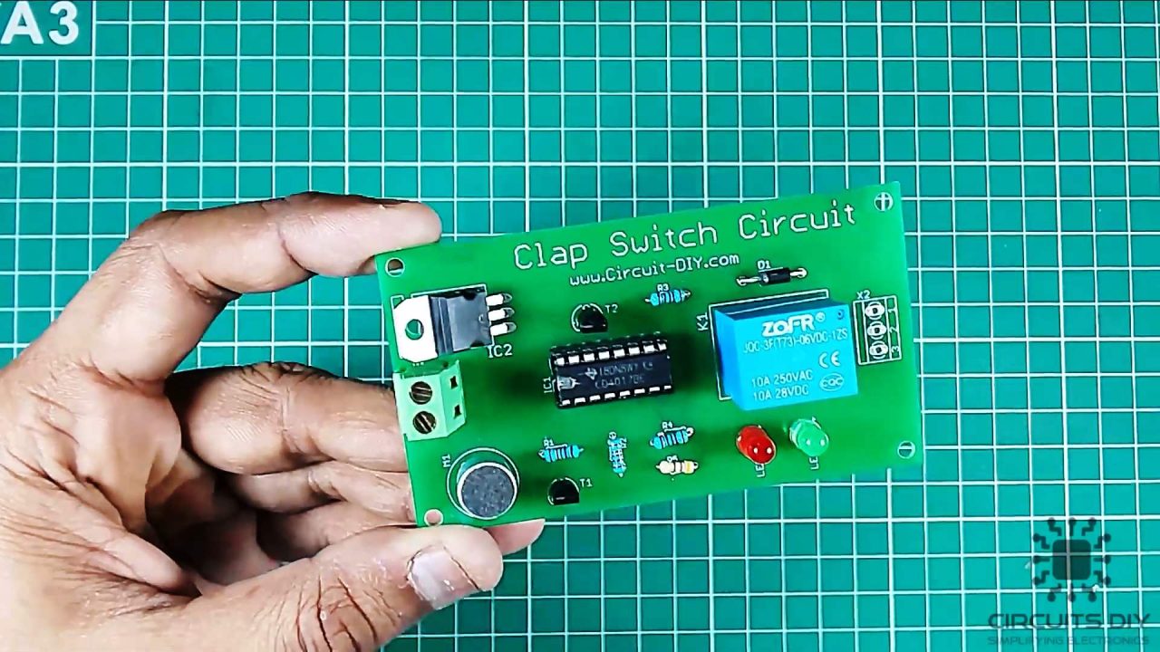
10) Power up and test the circuit using a 12V DC battery.

Working Explanation
The working of this circuit is as follows, the electret mic receives the audio noise input from a sound such as a clap, and transduces it into an electrical output. The output from the mic then acts as a control signal at the base of the BC547 transistor. The collector output from the transistor then serves as the clock input on pin 14 of the CD4017 counter IC.
The counter output Q1 then serves as the input control signal for the second BC547 transistor, triggering the output of the transistor to energize the coil terminals of the 5V relay. Here, we are using a flyback diode (1N4007) to protect the relay against any undesirable feedback in case of an electrical short. The collector output of the transistor energizes the SPDT relay, making any external circuit connected between the NC and COM terminal of the relay. Always choose a relay with respect to the input supply voltage supplied, and the output load I/V rating connected to the relay. This will help you in preventing damage to the relay.
Application & Uses
- Gaining dynamic control of AC/DC lighting fixtures.
- Also used in door locks and latches to gain remote access of rooms and places.


thanks for sharing the post i learn a lot from it