A simple and easy-to-make light sensor switch works with the detection of light in surroundings. The circuit uses only 5 components including the timer IC NE555 and LDR. The relay connects any electronic circuit to this one and hence, is controllable.

Hardware Components
The following components are required to make Light Activated Switch Circuit
| S.no | Component | Value | Qty |
|---|---|---|---|
| 1. | IC | NE555 Timer | 1 |
| 2. | Battery | 9-12V | 1 |
| 3. | LDR | – | 1 |
| 4. | Diode | 1N4007 | 1 |
| 5. | Relays | 12V | 1 |
| 6. | Variable resistor | 15KΩ | 1 |
NE555 IC Pinout

For a detailed description of pinout, dimension features, and specifications download the datasheet of 555 Timer
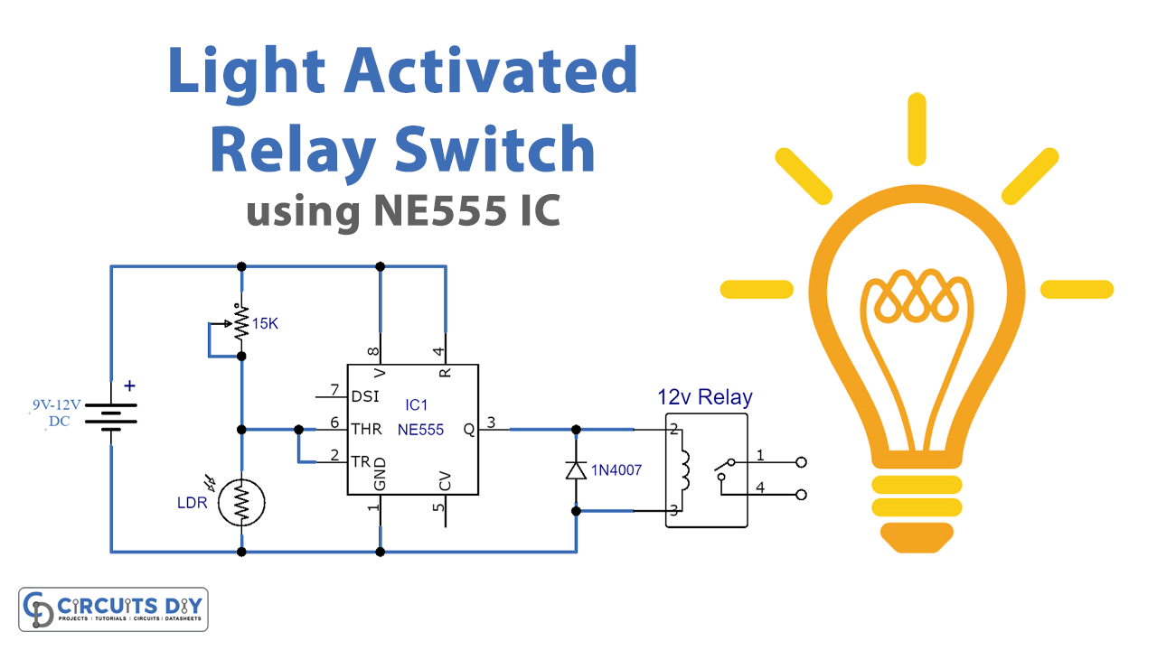
Light Activated Switch Circuit
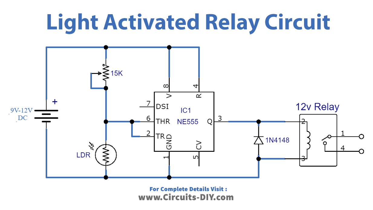
Working Explanation
Through LDR in the circuit, light detection takes place. As soon as light falls on LDR its resistance decreases. In this case, the input pin of NE555 goes high and IC NE555 starts its working. Till the set time duration, the IC PIN03 remains High. Furthermore, the 15KΩ variable sets the sensitivity of this circuit. The relay switch activates with the activation of NE555. A diode 1N4007 is attached to the realy to prevent back EMF to the relay switch. Moreover, the addition of an LED is also possible. For this purpose, connect an LED with a 470Ω current limiting resistor with the output PIN 03 of the IC.
The circuit operates at 9V to 12V of DC battery supply. Furthermore, the relay connects this circuit to external AC or DC circuits or appliances and hence, makes them operational.
Application
- Home automation of electrical load appliances.
- Light-controlled street light mechanism.