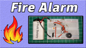
What is Roulette?
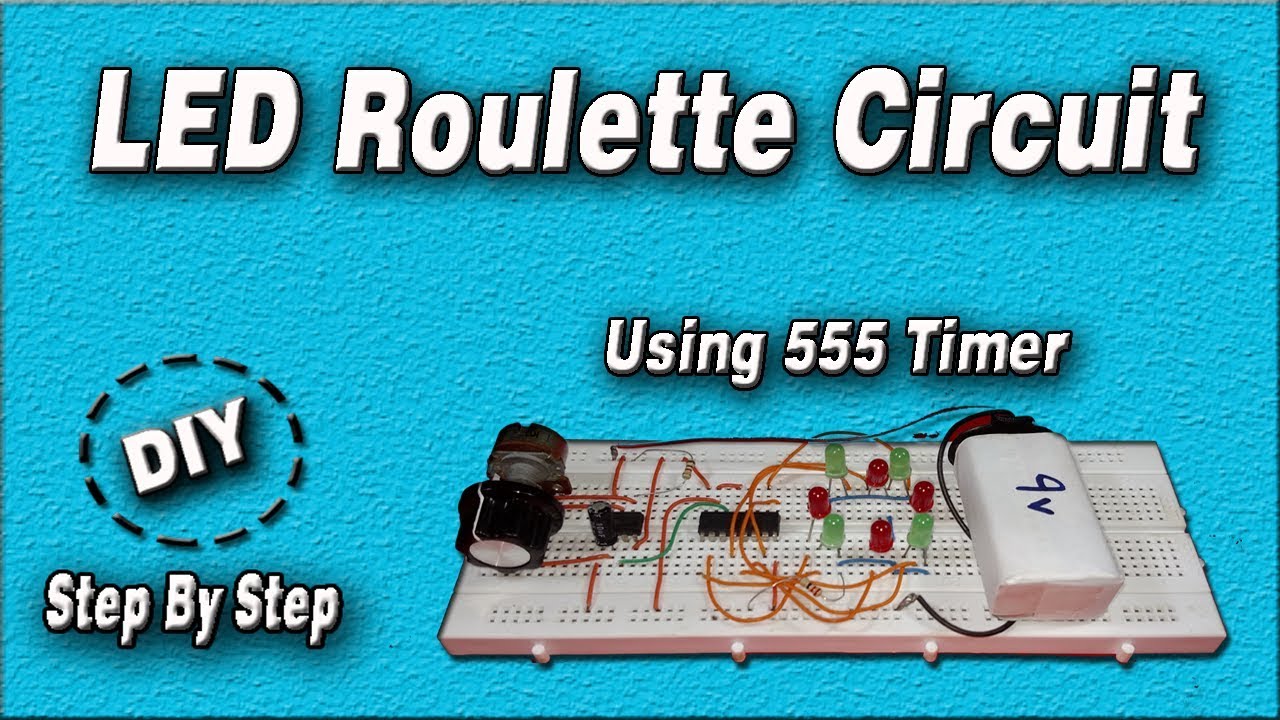
Roulette is a casino game named after the French word meaning little wheel. In this game, players may choose to place bets on either a single number, various groupings of numbers, or the colors red or black. So here In this tutorial, we are going to make an “LED Roulette Circuit using 555 Timer IC“.
The main component of this circuit is a NE555 Timer IC. The IC possesses an oscillation frequency ranging from 670 to 680 Hz. Here, this NE555 timer acts as an astable multivibrator. An astable multivibrator is a free-running oscillator that switches continuously between its two unstable states. With no external signal applied, the transistors alternately switch from cutoff to saturation state at a frequency that RC time constants of the coupling circuit determine. If these time constants are equal (R and C are equal) then a square wave will generate with a frequency of 1/1.4 RxC. Hence, an astable multivibrator is also a pulse generator or a square wave generator.

Hardware Components
The following components are required to make LED Roulette Circuit
| S.No | Component | Value | Qty |
|---|---|---|---|
| 1. | Breadboard | – | 1 |
| 2. | Connecting Wires | – | 1 |
| 3. | Battery | 9v | 1 |
| 4. | Decade Counter IC | CD4017 | 1 |
| 5. | IC | NE555 Timer | 1 |
| 6. | Resistors | 220 Ohm, 1k | 1, 1 |
| 7. | Capacitor | 10µF | 1 |
| 8. | LED | 5mm | 8 |
555 IC Pinout

For a detailed description of pinout, dimension features, and specifications download the datasheet of 555 Timer
CD4017 Pinout
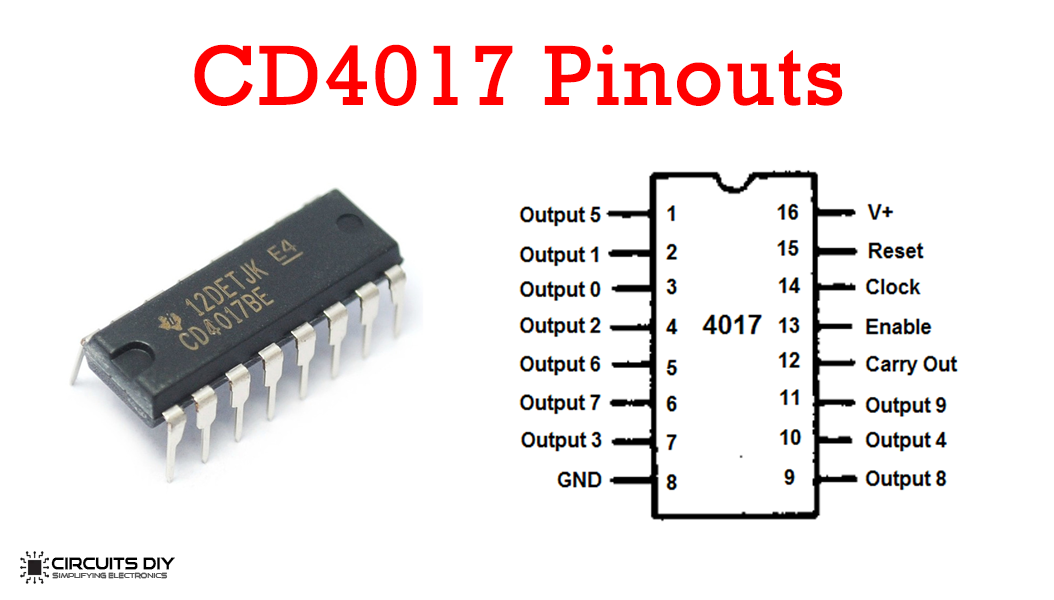
For a detailed description of pinout, dimension features, and specifications download the datasheet of CD4017
LED Roulette Circuit
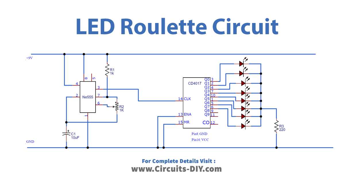
Working Explanation
In this circuit, the IC is used to generate output in a sequential manner; it starts from zero and goes up to 10. It shifts it to output from one pin to another by applying a clock pulse at PIN 14. The first clock pulse makes the first output PIN (PIN 3) HIGH, the second clock pulse makes the first PIN LOW and the second PIN (PIN 2) HIGH, the third clock pulse makes the third PIN HIGH, and so on. So it creates sequential ON and OFF of all the 10 Output Pins.
Applications
- Usually used in recreational activities for choosing a particular option in places such as casinos & shopping malls.