Introduction
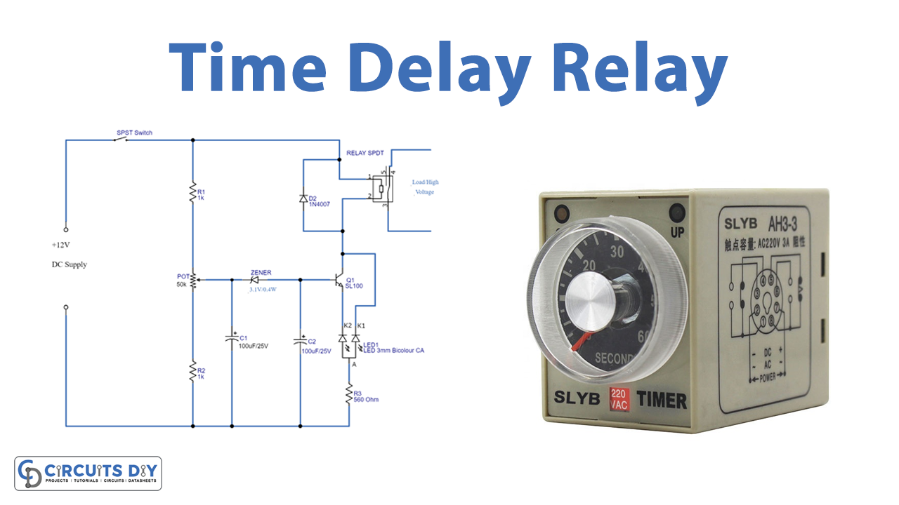
In this tutorial, we are going to learn about the “Time Delay Relay.” Time delay relays are generally known to those who work with electricity. As you know, that device is used to regulate high power while consuming very little electricity. These are also used for signal processing and can be used as switches. A standard relay is an electrical device that acts similarly to an electrically powered switch. One sort of relay is a time delay.
It is a well-known and often utilized tool in the power industry. The time delay relay works by changing the state of the contacts In the making of this time delay circuit, we require an NPN transistor, an SPDT transistor, and an SPST relay, along with some other components. Hence all of the components are listed below
Hardware Required
| S.no | Component | Value | Qty |
|---|---|---|---|
| 1. | NPN Transistor | SL100, BC547 | 1 |
| 2. | SPDT Relay | – | 1, 1 |
| 4. | LED | – | 1 |
| 5. | Zener Diode | 3.1V | 1 |
| 6. | Diode | 1N4007 | 1 |
| 7. | Potentiometer | 50KΩ | 1 |
| 8. | Electrolysis Capacitor | 100uf, 1000uF | 1, 1 |
| 9. | Resistor | 1KΩ, 560Ω | 2, 1 |
| 10. | DC Supply | 12V | 1 |
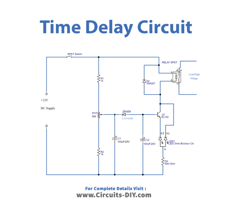
Circuit Diagram
Working Explanation
The voltage divider resistors and electrolytic capacitors serve as time delay components in the circuit’s first part. While the second part of the circuit is a relay with an LED indication. R1, R2, and potentiometer are wired in series and across to the DC input source. The potentiometer’s output is given to the C1 capacitor and the reverse biassed Zener diode. Finally, connect the C2 capacitor to the base of the SL100 transistor. The collector terminal of the SL100 transistor is connected to the collector terminal of the 12V relay, the green terminal of the Bicolor LED is connected to the emitter of Q1 and the red terminal is connected across the collector.
When power is supplied to this circuit, based on the value of the potentiometer, a tiny level of voltage is transferred to C1 and it charges. when it gets charged and goes above the cutoff limit of the Zener diode, a voltage is passed to C2 and it charges. When the C2 reaches the base-emitter voltage limit of the Q1 transistor, the transistor turns on. After the relay coil receives total DC power, the relay gets energized. The time delay depends on the potentiometer setting, C1-C2 charge time, & Zener diode breakdown voltage.
Thus, we can achieve a few seconds to a few minutes of time delay. Also, by changing the Potentiometer value or C1-C2 value we can achieve different time delay levels.
Application and Uses
- Industrial automation
- Flashing light control, etc