In this tutorial, we are making an Automatic Sequence Solar Battery Charger circuit. This circuit will automatically shift the charging from one battery to another when the first one is fully charged. When the second battery gets fully charged it will get shifted to the third battery and so on. In this way, solar energy is saved from being wasted as the solar panels still generate energy even when the battery gets fully charged.
Hardware Components
Solar Battery Charger Circuit
| S.no | Component | Value | Quantity |
|---|---|---|---|
| 1. | IC | NE555 Timer | 1 |
| 2. | Decade Counter Divider IC | CD4017 | 1 |
| 3. | LED | – | 4 |
| 4. | Zener diode | 3.3V | 1 |
| 5. | MOSFET | BUZ11 | 4 |
| 6. | Transistor | 2N4403, 2N3904 | 1, 4 |
| 7. | Variable Resistor | 100K | 1 |
| 8. | Resistor | 8.2KΩ, 1KΩ | 1, 10 |
| 9. | Capacitor | 10nF | 1 |
| 10. | Lead Acid Battery | 12V | 4 |
| 11. | Adjustable Power Supply(for testing) | – | 1 |
NE555 IC

For a detailed description of pinout, dimension features, and specifications download the datasheet of 555 Timer
CD4017
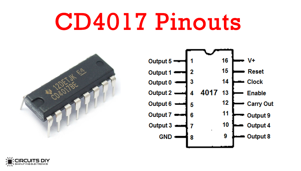
For a detailed description of pinout, dimension features, and specifications download the datasheet of CD4017
Solar Battery Charger Circuit
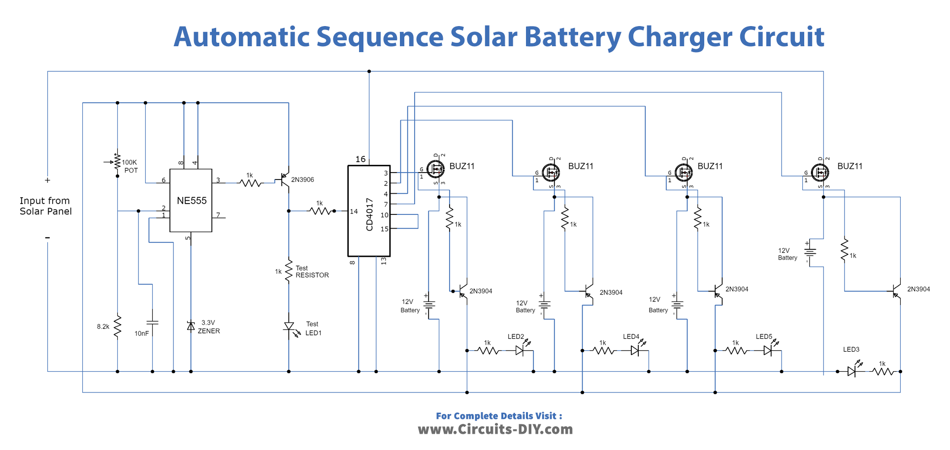
Working Explanation
Two ICs are used in this circuit. One is a 555 timer IC and the other is a decade counter IC CD 2017. The amperes going to the battery will depend on the output of the solar panel. So if you want to charge 100AH batteries use 10A output current solar panels and for 7AH batteries use 1000mA output panels.
The output voltage of solar panels must be any voltage ranging from 18V to 24V in all conditions. The four LEDs (LED1-LED4) are used for visual indication of the charging status of the battery getting charged. There are four BUZ11 MOSFETs used in this circuit. They should use proper heatsink to avoid overheating during the operation.
Circuit Adjustments
After you are done building this circuit make the following adjustments once initially,
- You will need an adjustable power supply to set the trip point of the charger circuit.
- Remove the solar panel and batteries from the circuit.
- Set the voltage to 15V in the adjustable power supply and connect it with the circuit.
- Now connect the LED and resistor as shown in the circuit diagram named test LED and test resistor.
- Disconnect pin16 of IC2 (CD 4017) from the positive rail during the adjustment.
- Now adjust the trip point variable resistor until the test LED turns on.
- Decrease the voltage of the adjustable power supply and then set it to 15V again. This will make LED go off and on again which shows that the charger circuit is now adjusted for charging.
- Disconnect the adjustable power supply, and test the LED and resistor from the circuit.
- Reconnect the solar panel and batteries to the circuit and reconnect the pin16 of IC2 to the positive rail. Now your circuit is ready to use.