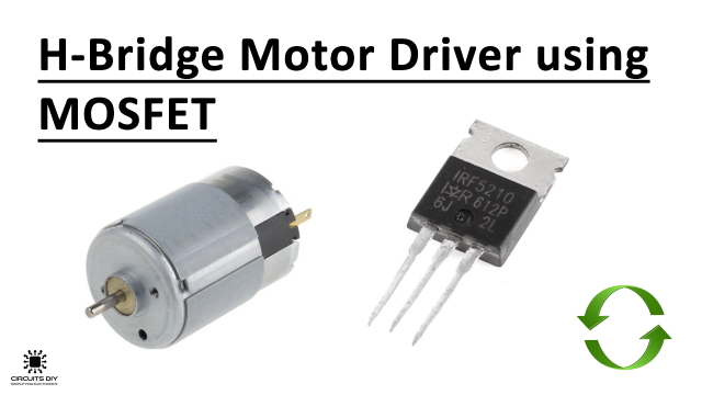
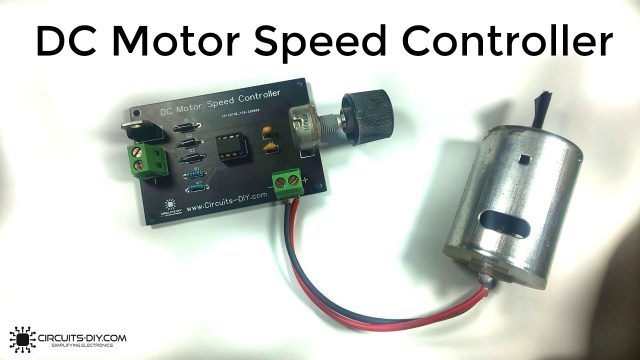
What is a DC Motor Speed Controller?
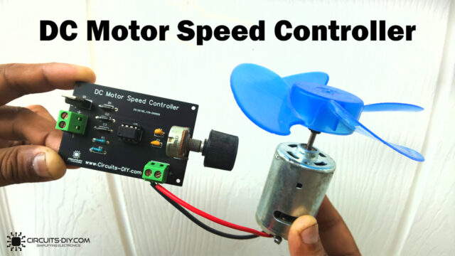
A wide variety of different methods can be employed to achieve speed & directional control of AC/DC Motors. A DC motor speed controller enables engineers & technicians to control the speed & direction of AC/DC drives in industries such as textile, mechanical & electrical for a number of different factory processes. In today’s tutorial, we will design a DC motor speed controller using a 2SC2625 power transistor.
The heart of this circuit is a 2SC2625 Power Transistor. 2SC2625 is a High Voltage High-Speed Switching Transistor. It is an NPN transistor in a TO-39 packaging, offering a max collector-base voltage of 450V & a collector current dissipation of 80W, so use an appropriate heat sink during transistor operation.
JLCPCB is the foremost PCB prototype & manufacturing company in china, providing us with the best service we have ever experienced regarding (Quality, Price Service & Time).
Hardware Required
You will need the following parts to build this project:
| S.no | Component | Value | Qty |
|---|---|---|---|
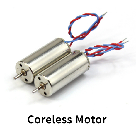
| 1. | DC coreless Motor | 60000rpm | 1 |
| 2. | Power transistor | 2SC2625 | 1 |
| 3. | Plastic Fan Blades | – | 1 |
| 4. | Potentiometer | 10KOhm | 1 |
| 5. | Soldering Iron | 45W – 65W | 1 |
| 6. | Soldering Wire With Flux | – | 1 |
| 7. | DC Battery | 3.7V | 1 |
| 8. | Jumper Wires | – | As per need |
2SC2625 Pinout
For a detailed description of pinout, dimension features, and specifications download the datasheet of 2SC2625
DC Motor
Useful Steps
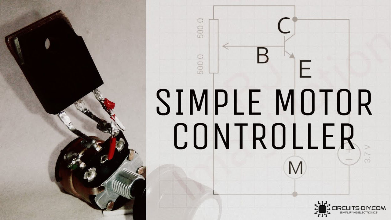
1) Solder the base & collector terminal of the 2SC2625 transistor with the wiper & fixed end of the 10K pot respectively.

2) After that, Solder the +ve & -ve terminal of the 3.7V DC battery with base terminal of the transistor & the fixed end of the 10K pot respectively.

3) Solder the +ve terminal of the coreless DC motor with the emitter of the transistor. After that, solder the -ve terminal of the DC motor with the fixed end of the 10K pot & the -ve terminal of the DC battery junction.
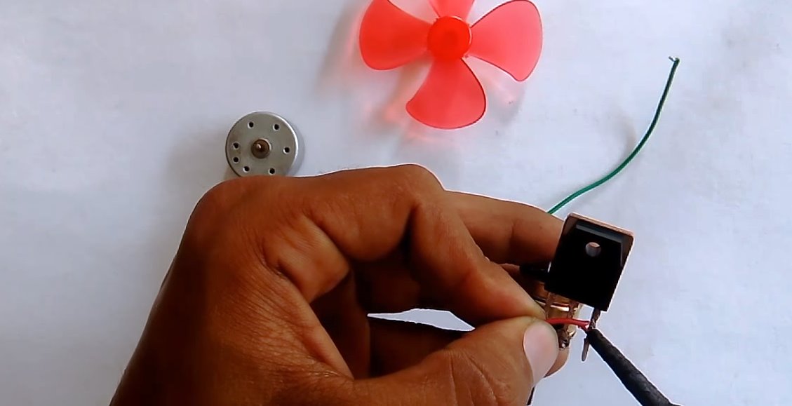
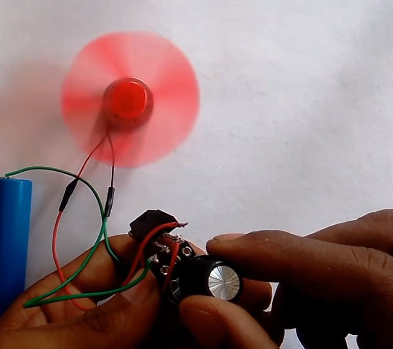
4) Attach the fan blades to the shaft of the DC motor. Test the circuit by slowly increasing the resistance of the 10K pot by turning the knob. The fans’ RPM will increase as you increase the value of the 10K pot.
Working Explanation
The working of this circuit is as follows, The 10K preset pot sets the control signal on the base of the 2SC2625 power transistor. On turning the knob of the preset pot, the resistance of the pot increases, subsequently increasing the control signal at the base of the Power transistor. The collector output then allows the shaft of the DC motor to rotate & the motor picks up speed.
On reducing the preset post resistance by turning the knob the other way, the control signal at the base of the transistor diminishes, consequently reducing the shaft speed (rpm) of the DC motor which slows down the DC motor.
Applications
- This circuit can be used to control the speed of DC motors, which can be consequently used in applications such as DC fans, motors, drones, etc.

